


Hi, I am working on my own script to be able to write to the registers of MCT8329A using i2c.
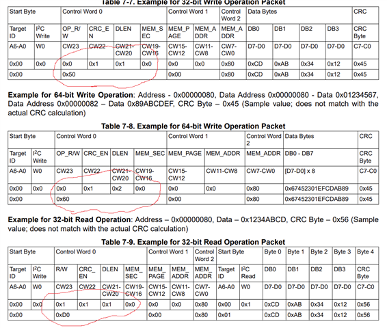
In the datasheet everything feels a bit contradictive. I for example don't understand these examples. Look at the marked areas. These values does not seem to correspond?
So my question is if there is any additional information hidden somewhere on how these bits and bytes are constructed?
If one could get a real example on how to write 4 data bytes into a register, that would be awesome.
As an example coult be writing to a device with address 0x60 to register 0x00000080 with 4 empty(0x00) bytes, without crc.
What are the exact bytes I will send for that?
What I have now i something like this;
  i2c.beginTransmission(0x60);
  i2c.write(uint8_t(0x20));
  i2c.write(uint8_t(0x80));
  i2c.write(uint8_t(register));
  i2c.write(uint8_t(byte1));
  i2c.write(uint8_t(byte2));
  i2c.write(uint8_t(byte3));
  i2c.write(uint8_t(byte4));
  i2c.endTransmission();
But that is obviously wrong.
So how would I do?
