This thread has been locked.

If you have a related question, please click the "Ask a related question" button in the top right corner. The newly created question will be automatically linked to this question.

DRV8701: Driver IC burnout

Part Number: DRV8701

Dear Sir/Madam,

We have developed Motor Driver Controller by using driver DRV8701ERGER and IRF40R207 Power MOSFET.

Controller action done through Embedded Software. This Motor driver are using for automatic door controller.

Our 4 nos. of Motor controller have been damaged during testing and we found that only DRV8701ERGER gets damaged.

We are unable to find the root cause failure, why the only DRV8701ERGER getting damaged. Rest circuit components are ok and not damaged like MCU, Power MOSFET and passive components.

I'm attaching schematic ,PCB layout and  Motor details for references.

Motor and Encoder.pdf  dc-motors-dc-direct-drive-brushed-motors-63-mm-194-and-255-watts-194-w-Part number-82890001.pdf

Regards 

Arvind Wagh

  • Hi Arvind,

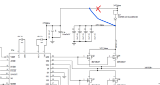
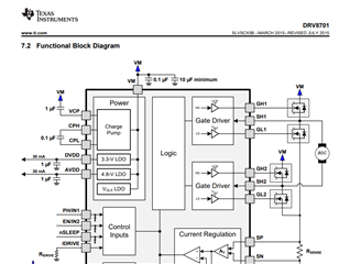
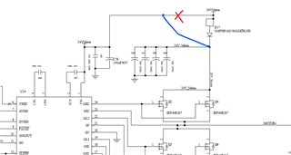
    Thanks for your post and thanks for the details. The HS FET DRAIN and driver IC VM must be directly connected. Else internal operation will not function as expected. For example dead time handshaking and VDS monitoring. Please see below and make this update.

    In addition to this please make sure when the motor is stopped abruptly all the energy may be dumped into the VM supply and could raise the VM voltage to above the absolute maximum specification of the driver and damage is permanently. A deceleration profile by slowly reducing the PWM duty cycle can help mitigate such issues. I have seen this happen with 24V supply and 24V motors.

    To rule out VM voltage pumping exceeding absolute max voltage you can monitor VM using an oscilloscope during your testing. If you see further failures this capture may help us diagnose the problem.

    Regards, Murugavel 

  • Dear Sir,

    Thanks for reply and suggestions.

    I have added Diode in between Driver and Motor supply to avoid the reverse voltage coming from Motor.

    This reverse voltage powered up the MCU and other system when diode just removed from circuit. I have observed that when the system is in power off condition and if we rotate the motor by hand clockwise or anticlockwise direction system gets powered ON for moment.To avoid such condition we added the diode.

    Please suggest any alternative to avoid such problem.

    Meanwhile we will monitor the Vm voltage using oscilloscope during testing for any abrupt changes and will check deceleration profile as well.

    Regards,

    Arvind

  • Few more points are as below,

    Regarding deceleration profile to stop motor.

    We are using this motor to control door opening and closing automatically. In case someone manually block door during open or close motion, we directly reduce PWM to 0 ,to change direction of the door. This is done for User safety. Suppose we slowly reduce PWM to 0 value then during deceleration still door will try to push user who is in path of door with greatest force.

  • Hello Arvind,

    I understand the use case, thanks for the details. Please check VM and ensure the voltage pumping is within the absolute maximum specifications. Were you able to make the circuit changes and test again?

    Regards, Murugavel

  • Dear Sir,

    Sorry for delayed response, it was back to back holiday.

    There is motor set-up to check the condition. Today will make set-up and will check the VM voltage with oscilloscope.

    Probably i will reply by today evening or tomorrow morning.

    Regards

    Arvind  

  • Hello Arvind,

    Sure, no problem. Thanks for keeping us posted.

    Regards, Murugavel

  • Dear Sir,

    As per your suggestions, i have monitored the Vm voltage on oscilloscope and its stable during operation and power ON/OFF.

    Recently more 3 nos. board damaged and DRV8701 burned out.

    In addition we also found that MOSFET also gets damaged but no burn mark on it.

    Current chopping Feature is Enable in Software by applying voltage to VREF Pin of DRV8701E.And Maximum current chopping is done for 9 Amp.So for overcurrent condition DRV8701 itself will chop PWM.

    Also on oscilloscope no change was observed in Vm Voltage for below situations,

    a)Powering On the controller

    b)decelerating PWM directly from 30% to 0%

    Can we use nFault pin Status to Prevent this situation? if yes How ?

    We would like to know any direct support from Texas for India or on call.

    Now this problem growing as all are boards are in Production.

    Reagard

    Arvind

  • Hello Arvind,

    Were all the boards modified as below?

    Can you get send us load current waveforms during start up and stop? Can you describe the exact failure mechanism - what procedure leads to a failure? So with the new failures only the driver was damaged and the output FETs did not fail? How often the failure happens? Does it happen only on certain boards with all boards?

    If you contacted your local TI sales office they may be able to get you local support. If they will not be able to resolve this issue they will escalate to our team in Dallas. We're supporting you already supported by us directly via this forum. Although there is a time difference between us this would be fastest as well as the best forum to get expert support from our team directly, which includes me. Thanks.

    Regards, Murugavel

  • Dear Sir,

    Thanks for support.

    I have added Diode in between Driver and Motor supply to avoid the reverse voltage coming from Motor. This reverse voltage powered up the MCU and other system when diode just removed from circuit. I have observed that when the system is in power off condition and if we rotate the motor by hand clockwise or anticlockwise direction system gets powered ON for moment. To avoid such condition we added the diode.

    We have observed that out of 40 nos. board ,30 nos. board have been found problem at motor startup and 10 nos. board result are awaiting. The problem has been found at Motor startup only at field site even though its tested ok at our production. The application of this motor controller are in Railways for Internal Compartment door control automatically.

    The all problem are found at Field and we are trying to recreate at our factory but not found yet. In our factory its working fine.

    As per your suggestions we have taken some snaps and videos for load current during startup and stop in our factory lab as below,

    A)Orange Trace - SP pin of DRV8701,Blue Trace - SO pin of DRV8701

    B)Orange Trace - PWM pin of DRV8701,Blue Trace - SO pin of DRV8701

    Also it is observed in 1 controller DRV8701E IC is entering in Current Chopping Mode for 3 Amp Current ,Although VREF voltage is set for 9 Amp Current.

    Oscilloscope waveform video as below,

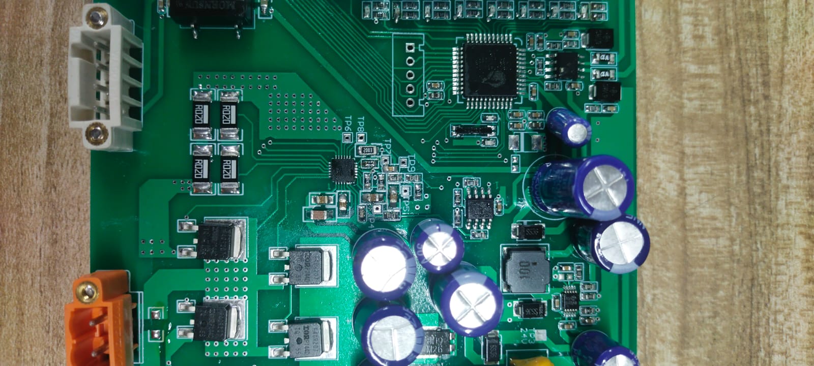
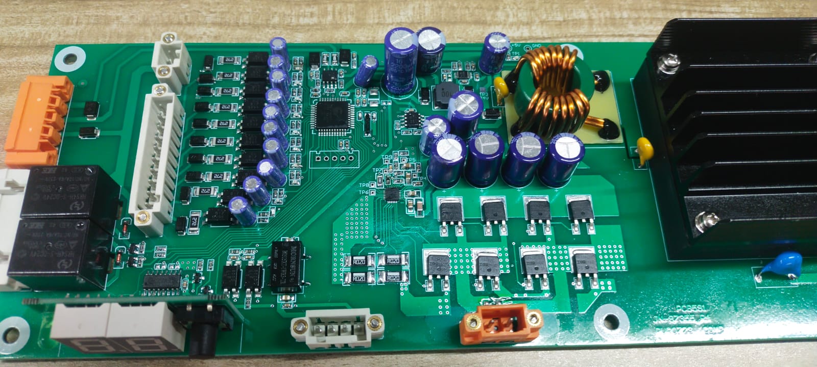
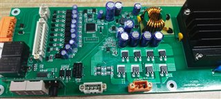
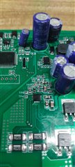
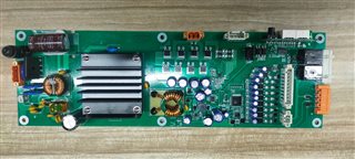
    Below are the actual board of Motor Controller attaching for your reference,

    Regards

    Arvind 

  • Sir,

    Please also let us know,how do we can measure the current in chopping mode.

    We seen that we are not able to measure current during chopping.

    Thanks in advance

  • Hello Arvind,

    Thank you for the details and oscilloscope output. You mentioned all 30 boards failed at startup. We need to focus on the startup situation. Is the motor fully loaded when started up? What is the length of the cable connecting the motor? Normally the driver does not fail unless it is electrically stressed beyond the absolute maximum specifications. Do you use PWM drive and ramp up the duty cycle to startup the motor or start it up at full speed with full load? Thanks.

    PS: If you have high bandwidth current probe you can get chopping current waveforms. Do you have one of our EVMs? Have you tried the same motor with our EVM?

    Regards, Murugavel 

  • Hi All,

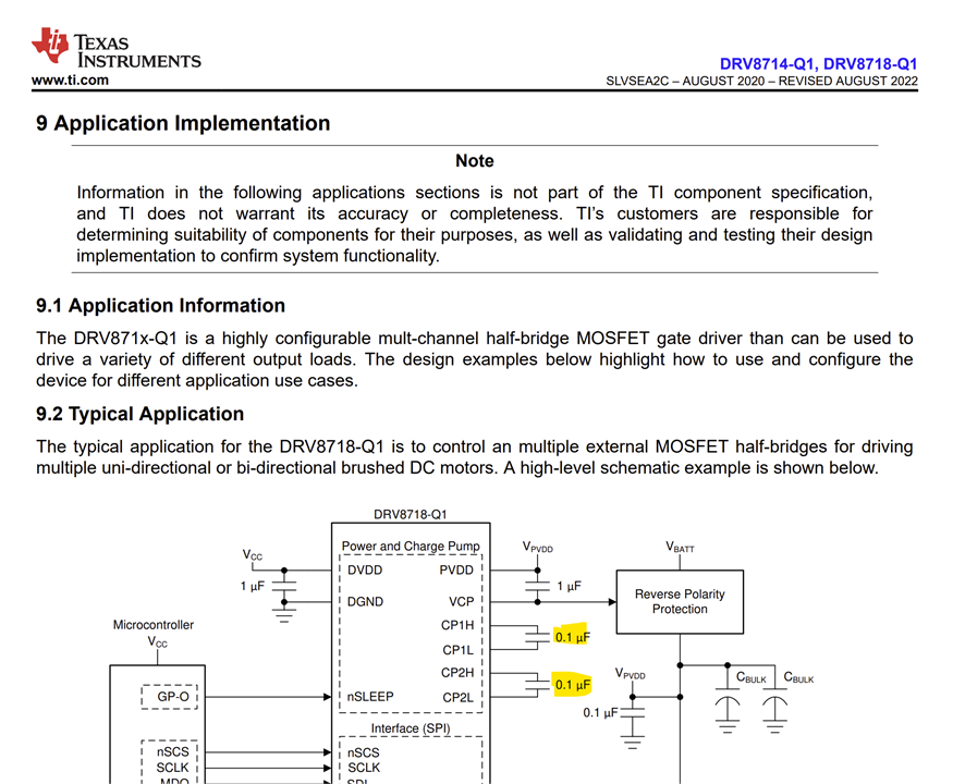
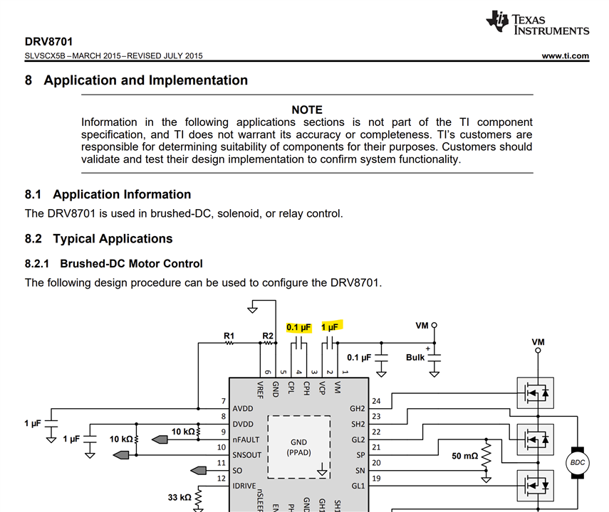
    I think C62 should be 0,1uF not 1uF.

    Regards,

    Grzegorz

  • Grzegorz is correct those caps should be 0.1 uF. Thanks.

    Regards, Murugavel

  • Hi Arvind,

    Sorry I mixed up the drivers. For the DRV8701 CPH to CPL should be 0.1 uF and VCP to VM should be 1 uF.

    Regards, Murugavel

  • Dear Sir,

    Thanks for observation.

    Please let us know 1uF value at CPL and CPH pin have any adverse effect on functioning of DRV8701.

    As we mistakenly added 1uF instead of 0.1uF value in 40 nos. Production lot.

    Is any relation with problem we facing of Driver burning ??

    Now we can see in factory setup its working fine and had problem at Field.

    Regards.

    Arvind

  • Sir,

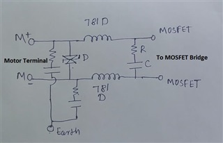
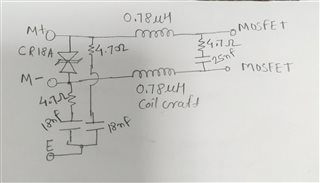
    Please also suggest any protection circuitry needed at motor terminal to avoid any excess voltage from Motor.

    Can below circuitry could help ?

    Regards 

    Arvind

  • Hi Arvind,

    1uF CPH-CPL capacitor may cause high VCP-VM voltage fluctuations plus may cause charge pump circuit overload and DRV8701 damage.

    I am not very familiar with BDC motors but circuit shown above looks like some EMI filter that may help reduce electrical noise caused by motor or/and driver. In this case you could consider using single CMM choke instead of two inductors.

    I think properly sized transil  diode (D) can protect against some overvoltages but has limited heat capacity in case of overvoltage caused by motor braking.

    Regards,

    Grzegorz

  • Dear Sir,

    We have been using this 1uF capacitor from 2 years and no DRV8701 damage found in development phase. Tried many cycles like nearly 10 k cycles.

    Now as we sent Controller to Field and then failure cases started coming.

    What will be the case of failure when using 1uF capacitor ?

    Should this external circuit will help for mitigating this problem ??

    Regards

    Arvind

  • Hi Arvind,

    "Should this external circuit will help for mitigating this problem ??" - I do not know, it may help - it may not.

    You are experiencing driver IC failure that can be caused by design errors as well by external factors.

    One serious design error was found by Murugavel, I gave you another one.

    Driver failure may be caused by many other factors like:

    - PCB layout, your board looks nice and well organized but H-bridge circuit has large parasitic inductances that may cause IC failure during work as well in case of strong electromagnetic fields

    - Is it possible to back drive the motor and cause overvoltage high enough to damage IC?

    - Are boards working in strong electromagnetic fields caused by other electric appliances?

    - Do failures occur during lightning?

    I would try to answer these questions.

    Making changes to the circuit like adding above mentioned filter + transil diode may help to find failure cause or/and prevent further IC failures.

    Regards,

    Grzegorz

  • Hi Arvind,

    We should identify the root cause of the failure in order to device a proper mitigation solution that would guarantee operation under all operating conditions. That's why I mentioned we should focus on motor startup because you specifically mentioned the failure happens during motor startup all the time. 

    Regarding this one capacitor issue you could change this in 5 boards, bypass the diode keeping the 1 uF (I understand the back-driving concern but this is for debug purpose) in 5 boards and change the capacitor and bypass the diode in 5 boards and conduct the startup tests with all 15 of these with a new DRV8701. During the testing you should monitor VM, Motor current, nFAULT line, and the power FET drains if separated by a diode. It would be useful if we get a capture at the exact failure moment. We have not come across any such massive amount of DRV8701 failures with any customer. We're keen in helping you resolve this issue as quickly as possible. Thanks,

    Regards, Murugavel

  • Dear Sir,

    Thanks for support and help.

    As per your suggestions, i will make this change in 15 nos. board.

    I have concern that could i get chance at customer end to try this possibility. I hope they should allow for this as its a production lot.

    Regards 

    Arvind

  • Sir,

    I will also try with this Filter + Transient diode to understand the source of problem is from Motor or other any aspect.

    Regards

    Arvind

  • Dear Sir,

    Few questions regarding the CPL-CPH capacitor in DRV8701,

    A)How do we differentiate the capacitor value affect the performance of Driver IC

    B)I have observed the waveform on oscilloscope with both 1uF and 0.1uF for gate voltage of external MOSFET which is comes same. No difference found for voltage levels at gate terminal of MOSFET.

  • Hi Arvind,

    Technically value of charge pump capacitor is not likely to cause any failures. The frequency for the charge pump is internally generated. The FET charging current strength may not be sufficient to charge up the capacitor fully and initial charge current may increase dissipation in the charge pump. I'm not sure if this would cause a failure. This is why I asked to include this step in one of the tests to see the difference. The difference could be 1 uF fails and other does not. But the failure could be related to some other issue. This is why it is important to fully understand the failure mode and what events mechanically or electrically that triggers it.

    For example we have had a situation where a user would force a door driven by the motor in one direction causing a large back EMF damaging the H-bridge driver. You have a diode in your circuit for this reason, however this separates an intended connection for the driver. There were situations where sudden stop of the motor and braking using the FETs may cause failure. So capturing the event that causes the failure is what we're looking for. Thanks.

    Regards, Murugavel

  • Dear Sir,

    Thanks for explaining Charge pump capacitor very nicely.

    We tried with below conditions,

    A)0.1 uF capacitor in 5 boards by keeping diode

    B)0.1 uF capacitor in 5 boards with bypassed diode

    C)Bypassed the diode and kept the1 uF in 5 boards 

    But in all above test condition DRV8701 burned out.

    From last few days, I was unable to create driver fail condition but now we are able to create the Driver IC failure. In below condition driver gets failed,

    A)We kept the 100 PWM speed and pushed door forcefully by hand opposite to door moving direction. Simulated this condition 4 to 5 times and Drivers gets failed. In this case no burring of DRV8701 and MOSFET damage were observed. DRV8701 damaged silently. During this condition ,Vm observed on Oscilloscope, no abrupt change or fluctuation found on oscilloscope.

    B)Without giving power to Driver Controller, we open close the door manually 4 to 5 times and then switched ON the power supply of Driver board. As i switched ON the power ,DRV8701 burns out and MOSFET also got damaged.During this condition ,Vm observed on Oscilloscope, no abrupt change or fluctuation found on oscilloscope.

    We also measured back emf of motor by moving door back and forth manually in power OFF condition. Oscilloscope probe kept on Motor Terminal M1 and ground. There is peak of 10V observed when door moves back and forth.

    Its looks back emf destroying the Driver IC and MOSFET.

    I also checked with protection circuitry ,even though DRV getting failed with above mentioned condition. Protection circuitry used as below,

    Diode rating 18V TVS Diode

    Regards 

    Arvind

  • Sir,

    We also have other Driver failure condition as below,

    We kept PWM to 100 and Door moving in forward direction, if we applied external force manually in same direction during forward moving it damaging Driver IC too.

    Can we use forward braking concept, if yes how we can implement it.

    Does it will solve Driver failure problem ??

    Regards

    Arvind

  • Hello Arvind,

    Thanks for all the details and thanks for the failure mode observation. This is what I suspected but wanted you to determine this explicitly. What is the MOSFET part # and specification used in the hardware?

    For condition A you may have to synchronize with the movement and capture with high speed to catch the voltage spike. 

    "We also measured back emf of motor by moving door back and forth manually in power OFF condition. Oscilloscope probe kept on Motor Terminal M1 and ground. There is peak of 10V observed when door moves back and forth.". This may not be the true BEMF. To get the actual BEMF when the door is manually slammed you will have to separate the motor wires from the board and measure the voltage across the motor terminals. 

    When the door is manually moved with driver not actively moving the motor the BEMF is conducted to the VM rail via the body diodes. This is why you inserted a diode in the VM path of the driver. There are two ways this BEMF voltage could damage the FETs. 1) The BEMF voltage rises above the absolute max. specs of the FETs. Potential solution: Use higher voltage FETs. 2) The current via the body diodes due to BEMF is beyond the max. current spec for the diodes and the body diodes may not be fast enough. Potential solution: Use higher current fast (Schottky) diodes in parallel with body diodes across the SOURCE and DRAIN of each FET. 

    I suspect the FET gets damaged first leading to the DRV damage. We replaced the power MOSFETs with a higher voltage TI HexFET that resolved the failure, https://www.ti.com/lit/ds/symlink/csd19535ktt.pdf. You may be able to order samples and try with these. They should be drop-in replacement.   

    You also mentioned you had failures even with the output 18 V clamping circuit which is puzzling. Even without connecting the motor terminals to the board if you have the clamping circuit across the motor terminals it should clamp the BEMF voltage to that level assuming the clamp absorbs the current fast enough with low impedance for a long duration. That said, the supply voltage of your application is 24 V. An 18 V clamp is not a good idea. It must be > 24 V. 

    Regards, Murugavel

  • Dear Sir,

    it's a IRF40R207 Power MOSFET. Datasheet attaached as below,

    Infineon-IRF40R207-DataSheet-v01_01-EN (1).pdf

    Please suggest diode part number for FET.

    Hardware are made for 8A Current rating.

    In part A) Only DRV failed and MOSFET are ok. And in B) Both DRV and MOSFET failed.

    Regards

    Arvind 

  • Please suggest it would help 

  • Hello Arvind,

    I looked up the IRF MOSFET datasheet based on the part# in the schematic you shared. These are 40 V FETs not suitable for 24 V BDC motor drives especially when there is higher BEMF and/or Vsupply pumping with energy back from the motor, because these conditions lead to higher voltages. In one example we measure up to a 70 V surge. It may or may not be the case with your application. You mentioned in part A MOSFET did not fail. It is not possible to say 100 % it was not even partially damaged.

    8 A current could be continuous rating. However when a DC is powered up with 100% duty cycle inrush current may be significantly higher. Likewise when the motor is stalled the current may be almost same as inrush current. This can be measured and confirmed.

    The external diodes will help only with BEMF situation but not with inrush or stall current related failure modes. Example https://www.digikey.com/en/products/detail/diodes-incorporated/SDT30B100D1-13/7667006.

    Regards, Murugavel 

  • Hi Arvind,

    Could you disconnect motor from the driver, connect motor leads to voltmeter and measure max. voltage when you try to

    move (open or close manually) the door as fast as possible?

    Regards,

    Grzegorz

  • Dear Sir,

    I tried this and Voltage goes up to 10V max.

    I am wondering if the motor in one direction and we applying external manual force in same direction.How it could damage the Driver IC.

    Could it possible in same direction voltage gets developed to damage the DRV ??

    Regards

    Arvind 

  • Hi Arvind,

    "I tried this and Voltage goes up to 10V max." - if it is just 10V when you try to push/pull the door as quickly as you can then 24V driver seems to be OK.

    Could you measure output voltage waveform on driver PCB with an oscilloscope while the door is moving freely and when you push the door against its moving direction (but not that hard to break the driver)? I would like to see how large is voltage ringing.

    Please turn off BW filter on your oscilloscope, oscilloscope should be connected between GND and motor terminal MOTOR+ or MOTOR-, the one that is PWM-ing. Then, please share waveforms or a video with these waveforms.

    PS.

    "I am wondering if the motor in one direction and we applying external manual force in same direction.How it could damage the Driver IC." - I think it is the most complex scenario, lets focus first on simpler case ie. when force is applied against door movement direction.

    Regards,

    Grzegorz

  • Dear Sir,

    As per your suggestions, videos have been taken for free and with forced conditions as below,

    A) Freely rotating condition,no external force  :

    B)Motor+ with ground and applied external force in same direction : 

    Huge spike observed with applied external force in same direction of Motor rotation 

    C)Motor - and Ground with external applied force: 

    No spike observed

    Regards

    Arvind 

  • Sir,

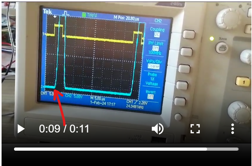
    Yellow Trace for applied PWM and Blue trace for Motor Voltages 

  • Hi Arvind,

    We have a problem with voltage pumping on second video, I will try to add more later during the day.

    Regards,

    Grzegorz

  • Dear Sir,

    Thank You for replying.

    Ok Noted 

  • Hello Arvind,

    Thanks for sharing videos.

    1. Can you make another video like the first one (door moving freely, quick acceleration/decelaration) but at 1us/div, please set trigger on falling edge and move blue channel 1div upward. I would like to see voltage undershoot at the end of falling edge.

    2. Can you tell what is roughly door weight (kg) and its max. speed (m/s) during applying 100% PWM?

    PS. Please use probe with 10x setting, it should give higher bandwidth.

    Regards,

    Grzegorz

  • Hello Arvind,

    In addition to those, for case B can you trigger on the rising edge pointed by the arrow? Reduce the voltage scale such that the full amplitude of the blue trace is captured. We need to see how much maximum voltage is pumped up during this condition. So during this testing did you have external TVS protection circuit or not? Thanks. 

    Regards, Murugavel

  • Dear Sir,

    As per your suggestions, waveform taken at below condition,

    Only Motor Voltages taken with respect to ground and  time base 1us/div,10x probe 

    A) Freely Moving

    B) Motor+ and ground with external force in same motor direction

    C) Motor - and ground with external force in same direction of Motor

    Roughly door weight (kg) = 30kg 

    its max. speed (m/s) =400mm/sec

    Max duty cycle 52% PWM

  • Dear Sir,

    Case B waveform with reduced voltage scale

    No TVS connected across the Motor terminal for now,

    However tested this condition with 18V bidirectional TVS diode

    Regards

    Arvind 

  • Hi Arvind,

    Thank you for all videos and data.

    Could you, please repeat measurement made on first video ie. freely moving, the same conditions but with timebases 250ns and 500ns.

    Please, adjust oscilloscope view so falling slope is close to the middle of the screen (horizontally). Just a small tip, it is usually easier to catch waveforms if "M Pos" (top of screen) is around 0.

    I will try to add more later during the day.

    Regards,

    Grzegorz

  • Hello Arvind,

    The max. kinetic energy that we have during normal work is equal to mv^2/2 = 30x0,4x0,4/2 = 2,4J.

    Total capacitance at VM bus is 4x330 = 1320 uF. Energy stored in capacitor is equal to CV^2/2.

    At 40V we have 1,056J and at 24V we got 0,38J, energy that can be stored by capacitors is 1,056-0,38 = 0,676J.

    Then I think there is some possibility that during normal deceleration kinetic energy of the door can cause VM voltage rise well above 40V unless it is lost due to friction. The possibility of failure will be higher in case door has smooth low friction linear bearings.

    Now if we take a look at videos where the door is pushed in the same direction as it moves we can see that motor voltage rises close to 40V, I guess similar voltage should be at VM bus. If it went higher there would be probably Mosfets and/or driver failure. Energies in that case could be much higher, lets assume someone pushes door with force 100N at 0,2m distance, if there was no friction losses we would get 20J back to VM bus. I think there is quite high probability of damage to the driver due to regenerative braking (voltage pumping) if someone pushes the door.

    "I tried this and Voltage goes up to 10V max." - Max. motor voltage is significantly lower than VM voltage then I guess there would be at least 3 ways of dealing with that problem:

    1. In case of increased VM voltage switching driver into High-Z state

    2.  In case of increased VM voltage switching driver into slow decay. Max. current would be around lets say 30V/(Motor + wiring/Mosfets resistance) = 30/0.9 Ohm = 33A.

    3. Use braking chopper or other device that would take energy out of VM bus in case excessive voltage rise.

    If I wanted to try option no 3 and I did not have any braking chopper I would try to use some really large unidirectional TVS diode on VM bus (parallel to VM capacitors) like  8.0SMDJ26A soldered on some large piece of copper on PCB. Before using it I would check its turn on and turn off voltages with regulated power supply and current limit set to 0.1-0.2A.

    Below mentioned blog may be helpful to understand the problem

    https://e2e.ti.com/blogs_/b/industrial_strength/posts/art-of-stopping-the-motor-vm-pumping

    My second suspect is not good H-bridge pcb layout that is compensated by quite long rise/fall times of around 0,5us but I think it would take some time to form an opinion on that matter.

    Regards,

    Grzegorz

  • Dear Sir,

    I have find the Voltage waveform during the failure of DRV as below,

    Measured between Motor terminal and ground with external manual force.

    Regards

    Arvind 

  • Hello Arvind,

    I see almost 40 V peak in one of the instances. It seems like it may get even higher with a little bit more force on the door. Thanks to Grzegorz. He has already provided you with thorough analysis of what's causing the voltage pumping and three options to mitigate failure as well as point you to the e2e post on art of stopping the motor. I have nothing else to add with the exception of the below comment.

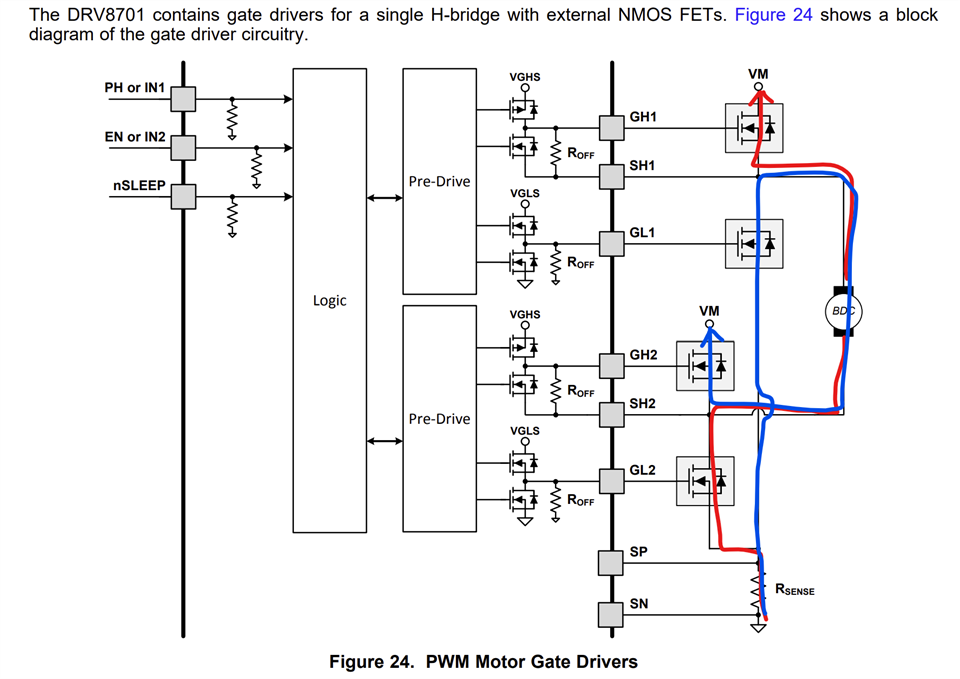
    The absolute max. VDS breakdown of the FETs on board is 40 V. The absolute max. for the DRV8701 is 47 V. The FETs on your board is currently the weakest link. I am assuming you still have the diode in series. The Schottky diode you have is a 90 V, 8 A diode. Bottom line with the diode the pumping hits only the FET DRAIN, see second image - snippet from schematic. I already suspected this, hence recommended higher voltage FETs. Going with the higher voltage FET has helped solve this issue in a similar issue with a different application. This does not guarantee full resolution for you but it is worth trying because you won't have to redo the PCB. Just need to change the MOSFETs. 

    As an alternative mitigation you design a voltage clamp at the 24V Motor node. Then you have to make sure the body diodes of the FET are capable of passing that energy without failure. Else you have to connect Schottky diodes across all four MOSFETs parallel to the body diodes.    

    The VDS breakdown voltage of the FETs is 40 V from its datasheet. This will lead to FET damage and subsequently driver damage. There could other instances such overstressing may happen in your use case. 

    Regards, Murugavel

  • Dear Sir,

    Thanks for explaining the Nature of problem.

    I would try with TVS diode and will update you for same.

    Meanwhile i will Also take possibility of other options.

    Regards

    Arvind 

  • Dear Sir,

    Thank you.

    I would replace the MOSFET with higher Voltage and will try to simulate the Failure condition.

    I will take step by step action as below,

    A)TVS diode across VM

    B) Higher voltage rating MOSFET as you suggested

    C)Schottky diode across drain to source.

    I will do above changes and will update you for same.

    Regards

    Arvind 

  • Hello Arvind,

    On your last video voltage goes down to around -6.5V (voltage undershoot), it is not a very large value but it may already cause problems. If planned steps do not help we may need to take a look on pcb layout as well.

    Regards,

    Grzegorz 

  • Hello Arvind,

    When you use TVS diode across VM or a clamp keep in mind this will cause a braking effect on the motor and the door has to be pushed harder as well as TVS should be sized to absorb the energy for that duration else it will fail. Also it must be > 24 V with some headroom. 

    Regards, Murugavel

  •  Dear Murugavel sir and Grzegorz sir,

    I'm really thank for your help and support to mitigate the driver failure issue.

    After making below changes in the board ,driver failure issue has been solved.

    1)The HS FET DRAIN and driver IC VM connected together after diode. Please see below

    Vm pin of driver IC tie to MOSFET drain does not help to solve the problem alone. In this condition we also faced the IC failure issue.

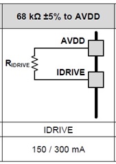
    2) IDRIVE resistor setting changed as below,

     IDRIVE resistor setting alone doesn't solve the problem.

    Its a cumulative effect of above two changes.

    Its VDS OCP monitoring and internal handshaking signal helped to solve problem as suggested by Mr.Murugavel.

    Below OCP condition might helped to protect the Driver IC and MOSFET failure.

    The Diode was creating difference of 0.7V for DRV IC and MOSFET drain and leading to miss of synching between the same.

    We have checked the 5 nos. of board very rigorously with by applying external force in direction of motor rotation.

    No failure observed during testing and on field as well.

    Regards

    Arvind