This thread has been locked.

If you have a related question, please click the "Ask a related question" button in the top right corner. The newly created question will be automatically linked to this question.

DRV8434: not getting a sin wave current

Part Number: DRV8434

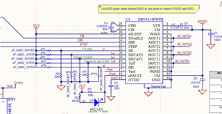
I designed my driver based on the eval kit since I had tried my stepper motor with TI0 DRV8434 Eval kit and it was working just fine. Now when i monitor the Current sent to the motor by my driver board, i can only see a DC signal instead of the sine wave! and of Course motor doesn't move.  the step signal sent by MC looks fine. im using DRV8434 with 48V and 1.7Arms, 1/4 ustep and smart tune, ripple control.

  • Hey Zeinab,

    Can you post your circuit schematic?  

    Do you have a voltage on the VREF pin? 

    Please start debugging this by probing each of the input signals on the Eval kit and compare to the signal/voltage on your new board and see what is different.  Also make sure you have all the required external components populated properly especially the charge pump capacitor.  

    Best,

    Jacob

  • Hi, here is the schematic,

    yes, Vref shows the torq im sending, so the DC current im probing on motor wires are what they should be (1.7Arms), im using a 0.022uf cap between pin27 and pin28.

  • to compare between my board and Eval board, i measured the voltage on caps on pin.15 (5V), between pin27 and pin28(48V), pin1 and pin2 (4.8V vs. 5v) so all the voltages are pretty much the same. However when i monitor the voltage on motor connector, i see unlike Eval, i have only switching voltage signals on two wires and the other two are constantly zero. so the bridges are not working properly. what could be the cause of it considering my schematic?

  • Hi Zeinab,

    The schematic looks fine. It may be possible the device was damaged. Do you have another device that you can try with. One more thing to look at is having the correct A and B pairs connected to OUT A1,A2 & OUT B1,B2. Verify the motor wires for A and B pairs with an ohmmeter and mark them such that they don't get mixed.

    Regards, Murugavel 

  • I have tried 4 PCBs all just arrived from PCB house, so i am not sure what is the possibly of receiving 4 new but damaged  DRV8434. for motor connections, OUTA1 and A2 is connected to one motor inductor and OUTB1 and B2 is connected to the other one. the order in wire 1 and 2 does not make a difference as far as i know.  Also considering my schematic if i do not connect any motor or connect it in a wrong way, the Fault LED must turn up.

  • Hi Zeinab,

    The odds of 4 PCBs having a damaged DRV8434 is very rare barring any handling issues at production. You're correct as long as the coil pairs are correctly connected the polarity does not matter. 

    The comment you made in your previous post that one pair of outputs are working and the other pair is not, was the reason for my suspicion of the connections. Based on the fault condition summary table whenever the driver disables the H-bridge for protection nFAULT is always asserted. As well as with all these protection modes when a fault condition is detected both bridges are disabled.  

    I am assuming you have double checked the layout footprint and the traces for matching the schematic. Make sure that both pin-2 and pin-13 are connected and receiving the VM voltage. Likewise PGND of both H-bridges pins-3&12 are connected (continuity check) and connected to GND. The schematic looks correct. 

    Regards, Murugavel

  • Hi, Thanks for the explanations, the layout is all right. i still went ahead and replace the chip and it solved the problem. it actually was the case of handling issue. it looks fine now. Thank you!