This thread has been locked.

If you have a related question, please click the "Ask a related question" button in the top right corner. The newly created question will be automatically linked to this question.

DRV8706-Q1: Setting (Level 1-6) overcurrent on hardware version of this driver chip.

Part Number: DRV8706-Q1

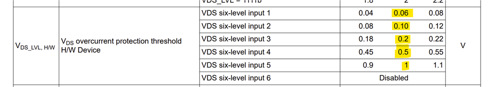
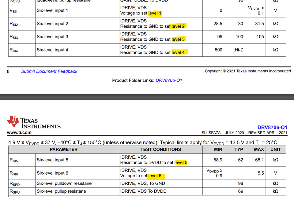
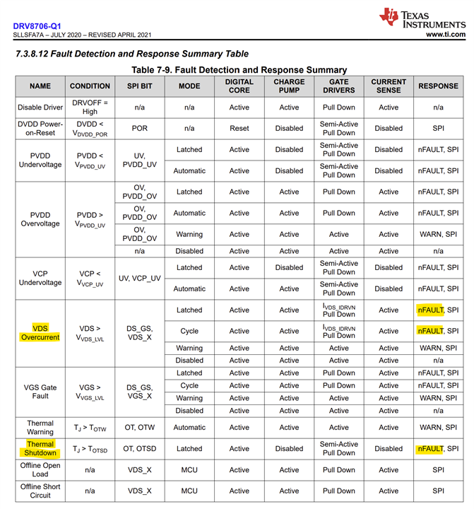
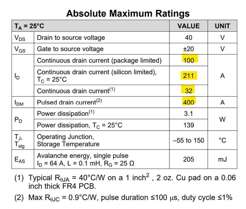
I am using the hardware version of this chip.  I have a board built and successfully running brushed motors.  I did my calculations for the various control resistors based on 100A max.  I currently have the overcurrent protection disabled (pin 4 VDS tied to DVDD) because I couldn't figure out how to set the resistor divider to feed the overcurrent control pin 4.  I couldn't make out what the Level 1-5 meant in terms of max current.
Can someone please advise?

Ideally, I want to set it to kick in around 70 or 80A.  But I still want to understand what each level would represent if the calculations were based on 100A.


Sincerely,

Craig Kessler
AndyMark, Inc.

  • Hi Craig,

    The VDS levels highlighted in the below snippet are selected based on the level voltages (resistors to GND) suggested for this 6-level input pin, shown in the second snippet.

    VDS voltage is the I*R voltage drop across the MOSFET, which would be load current * Rdson of the FET. Let's say the Rdson of the FET is 10 mΩ, with 100 A the VDS voltage would be 100 * 0.010 = 1V. So VDS pin should be set for level 5. I hope this helps. 

    Note: OCP will be detected after overcurrent deglitch time tDS_DG, H/W lapses, 4 us typical for this device. This must be kept in mind for short circuit protection with a dead short at the output. It is possible to damage the FET before OCP kicks in. A small inductor such as a ferrite bead may be required on board at the output terminal to slow down the di/dt for short circuit protection.

    Regards, Murugavel

  • Thanks for the fast response!
    If overcurrent protection kicks does the fault pin get set?

  • Hi Craig,

    Yes it does. See the 7.3.8.12 Fault Detection and Response Summary Table in the datasheet.

    Regards, Murugavel

  • 1) When I looked at the EVM board and schematic, they just ground the Vds pin for Level 1. But the datasheet shows 0.04V to 0.08V.
    2) Also, if I solve for Current limit thresholds when RdsON = 1mOhm nominal for my MOSFETs
    I get

    Current Limit Equation Rdson (Ohms) Level (Voltage nominal) Level number
    60 Icurrentlimit = Vdslevel/Rdson 0.001 0.06 1
    100 0.1 2
    200 0.2 3
    500 0.5 4
    1000 1 5
    Disabled DVDD (3.3V in my case) 6

    That means that in my case, the best I can do is either set the limit to 60A or 100A.  That means this feature would become useless if I had an even lower RdsON MOSFET.  Or am I missing something?

  • Hi Craig,

    VDS threshold 0.06 V typical is the lowest available threshold in this device. Hence that was selected in the EVM. You are correct with the calculations. 0.06 V threshold may not be the best lowest threshold for ultralow Rdson FETs if you want to detect lower than 100 A threshold for OC. Ultralow Rdson FETs are also meant for super high inrush currents and they'd survive very high pulsed current, 100's of A. Ideally a latched overcurrent fault should be used with such low Rdson FETs.

    See below absolute maximum ratings of the FETs used in the EVM hardware.

    Regards, Murugavel