This thread has been locked.

If you have a related question, please click the "Ask a related question" button in the top right corner. The newly created question will be automatically linked to this question.

DRV8871: Drive electromagnet

Part Number: DRV8871
Other Parts Discussed in Thread: DRV8870, DRV8873, DRV8243-Q1

Hi Team,

Q1:

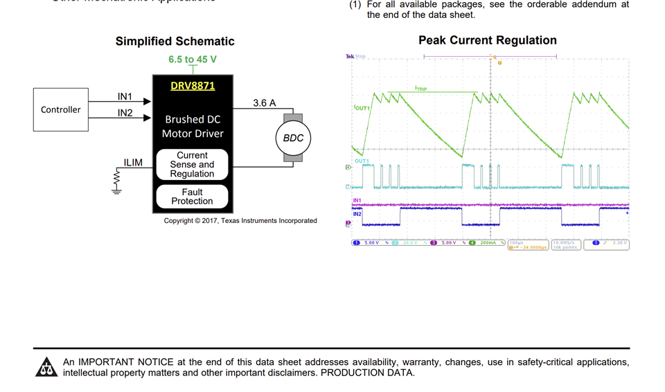
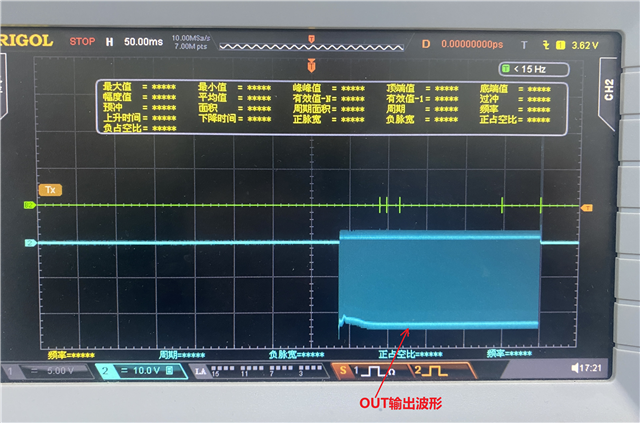
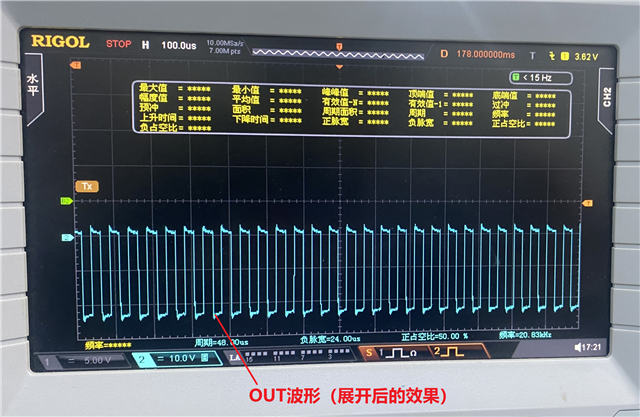
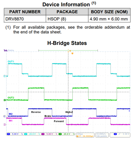
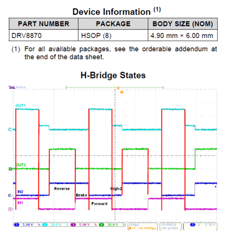
The input terminals IN1 and IN2 of DRV8871 input static data. For example, IN1=1 (high level), IN2=0 (low level), the duration is 200ms, then IN1=0, IN2=0, and the period is 2 seconds. It is found that the OUT1 and OUT2 outputs of DRV8871 are PWM waveforms with a duty cycle of 50% and a duration of 200ms (the same duration as IN1=1 and IN2=0). Why is the OUT output PWM instead of a continuous fixed level?

The loads connected to OUT1 and OUT2 of DRV8871 are bidirectional holding electromagnets (this electromagnet can be powered forward or reversely; when powered forward/reversely, the metal column of the electromagnet can pop up/retract) . OUT1 is connected to the positive pole of the electromagnet, and OUT2 is connected to the negative pole of the electromagnet.

DRV8871 cannot drive the solenoid. Is this the reason? 

Q2:

Could you please recommend a driver that can drive an electromagnet (solenoid)? Power supply = +24V, OUT output current ≥ 1.2A, driver input terminal is level controlled (such as IN1, IN2). The customer doesn't want to use PWM control.

Regards,

Annie

  • Hi Annie,

    It appears that peak current regulation was kicking in. Did the customer try with RLIM = 15 kΩ ? Having the ILIM set to 64/15 = 4.27 A should not kick-in regulation assuming the solenoid current does not exceed 4.27 A. What value of the RLIM was used? Can you share the output current waveforms when the solenoid is enabled from rising edge to steady state current?  


    Regards, Murugavel

  • Hi Murugavel,

    RLIM external resistor is 30kΩ.


    Regards,

    Annie

  • Hi Annie,

    This is the voltage waveform. Can we get current waveform using a current probe? Can the customer try with 15 kΩ? What is the specifications of the solenoid DCR and inductance? 

    Regards, Murugavel

  • Hi Murugavel,

    The DC regulated power supply outputs +24V 1.4A to power the DRV8871. When soldering RLIM to 15kΩ, the OUT output is high level (no longer a PWM waveform).

    But an abnormal situation occurred. Previously, when RLIM=30kΩ, IN1=1 (high level), IN2=0, the duration was 260ms (IN1 and IN2 were output by FPGA), and OUT output a PWM waveform of 260ms. But when RLIM is changed to 15kΩ, IN1=1 (high leveling) becomes 60ms (but the FPGA program does not change), and the OUT output high level time is also 60ms. It looks like the DRV8871 is affecting the FPGA output.

    The customer's current testing conditions are limited. He does not have an AC probe, so he cannot test the current waveform. The DCR of the electromagnet is about 8Ω (data obtained by testing both ends of the electromagnet with a multimeter)

    In addition, can DRV8871 drive a bidirectional electromagnet (bidirectional electromagnet can be powered forward/reversely)? The customer learned that the DRV8871 cannot drive solenoids.

    Regards,

    Annie

  • Hi Annie,

    Sorry I'm trying to understand exact details. Can you please post input and output waveforms for both 30k and 15k RLIM cases. If no AC probe customer can use a power resistor like two or three 1 ohms in parallel and capture the voltage across it. Note the ground of the probe should be isolated and not conflict with other channel ground input of the scope.

    DRV8871 is an H-bridge show forward and reverse driving polarity will be supported. "The customer learned that the DRV8871 cannot drive solenoids.". Could you please elaborate this? Does the solenoid not actuate at all when tested? Is the customer using our EVM? Thanks.

    Regards, Murugavel

  • Hi Murugavel,

    1. When RLIM=30k, the electromagnet can be turned on/off normally, but it requires a larger current from the external DC regulated power supply (output current of the external DC regulated power supply ≥1.2A. When the output current of the external DC regulated power supply is less than 1A, the electromagnet sometimes opens or closes abnormally). If the output end of the DC regulated power supply is directly connected to the electromagnet, the electromagnet can be turned on/off normally when the output current of the DC regulated power supply is 0.8A.

    2.

    "The customer learned that the DRV8871 cannot drive solenoids.". Could you please elaborate this? Does the solenoid not actuate at all when tested? Is the customer using our EVM?

    The DRV8871 driver board is a board purchased online, not TI's EVM board. In fact, it was not that he encountered the ""cannot drive the solenoid"" problem, but he saw it in E2E's post, so he wanted to confirm "whether the DRV8871 cannot drive the solenoid"?

    https://e2e.ti.com/support/motor-drivers-group/motor-drivers/f/motor-drivers-forum/642492/drv8841-why-drv8871-is-not-suitable-for-solenoid-driving

    3. The customer believed that DRV8870 was more suitable for his design needs. Are there any special differences between DRV8870 and DRV8871?


    Best regards, Annie

  • Hi Annie,

    Can we get datasheet for the electromagnet? What is the L and R as well as specified voltage and current specs for the electromagnet.

    Regards, Murugavel

  • Hi Murugavel,

    I'm waiting for the customer to provide information about the electromagnet.

    And I have updated the above Q2 and Q3, can you help me take a look?

    Regards,

    Annie

  • Hi Murugavel,

    The electromagnet was purchased online. The manufacturer was on holiday and some parameters were not available. 

    1. The maximum instantaneous current of the electromagnet is <4A; as long as normal operation can be guaranteed, the smaller the current, the better;

    2. Power supply voltage: DC +24V

    3. Use the short circuit setting of the multimeter to test the two lead ends of the electromagnet. The resistance value is about 8 ohms.

    Regards, Annie

  • Hi Annie,

    Thanks for the information. First let me comment on 2 and 3. 

    2. The final comment was "Assuming the voltage and current requirements can be met with the DRV8871/2, it should be able to control a bistable latching solenoid.". But there was no closure with why it was not in the selection guide. In general as long as the voltage and current drive requirements match it should work.

    3. The difference would be the current regulation scheme. See below. This requires external current sensing resistor vs. Rlim resistor on the DRV8871. Customer can use the DRV8870 if they prefer to use it. If current regulation is not required the Rsense can be a short or 0 ohms and connect VREF to 3.3V or 5V. The current will be limited by the electromagnet DCR, 8 ohms, so 3 A. 

    Regarding the electromagnet, 24V and 8 ohms will mean a steady state load current of 24/8 = 3 A. The customer power supply should be capable of providing > 3A without significant decrease in 24 V (ripple voltage). For the DRV8871 Rlim 15 k would mean 64/15 = 4.3 A, so there won't be current regulation. I'm not sure what caused abnormal waveform. Can we get input and output waveform taken with two channels?

    Also for both devices keep in minds peak current spec is 3.6 A. With 3 A power dissipation will be > 3x3x Rdson 565 mohms which would be > 5 W. This will heat the device fast and cause thermal shutdown TSD. I think this was what happened in the second test - abnormal output device already shutdown - customer can measure the temperature of the device with a probe or thermal camera. For this current spec customer must use a much lower Rdson device. For example DRV8873 https://www.ti.com/lit/ds/symlink/drv8873.pdf or DRV8243-Q1 https://www.ti.com/lit/ds/symlink/drv8243-q1.pdfThanks.

    Regards, Murugavel