This thread has been locked.

If you have a related question, please click the "Ask a related question" button in the top right corner. The newly created question will be automatically linked to this question.

DRV8452: HW - interface, Im not able to set microstepping or auto-interpolation

Part Number: DRV8452
Other Parts Discussed in Thread: DRV8462, DRV8434EVM

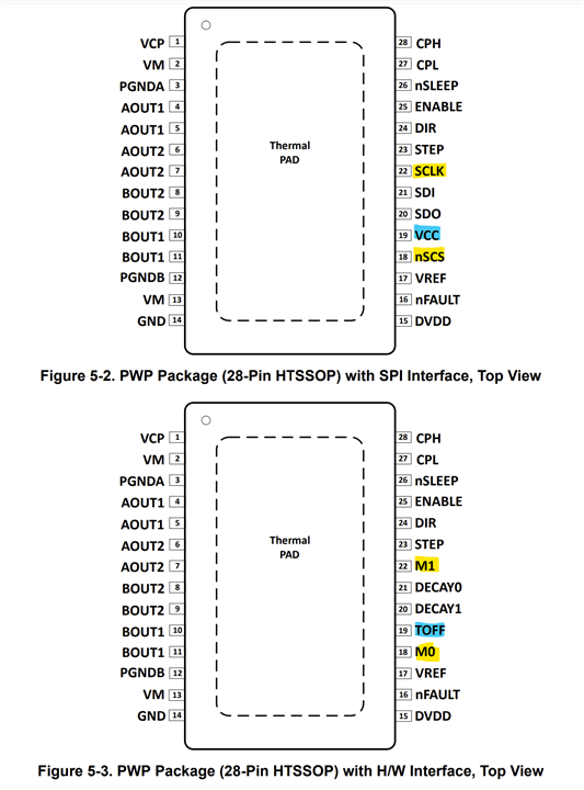
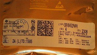
Hi, I have DRV8452PWP (HWinterface, not SPI)
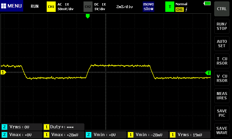
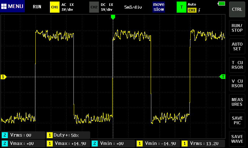
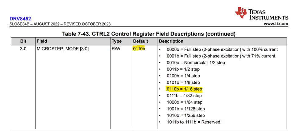
but when I connect the board to waveform generator, it goes like one pulse = one step of motor, that would be fine if i would set it to 1/1 microstepping (as I understood datasheet), but I have set some microstepping (before powering it up) but nothing changed. Motor steps are pretty hard so it must be 1/1 stepping. If i try to short some of M0/M1 to ground while motor is runnig, there is no difference.

Im using NEMA23 at 24V (SY57STH76-2804A)
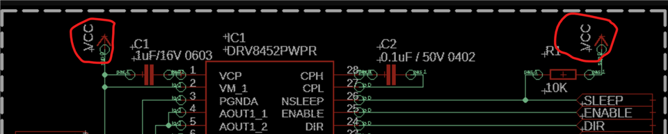
Here is my schematic: (just prototype)


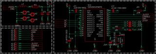
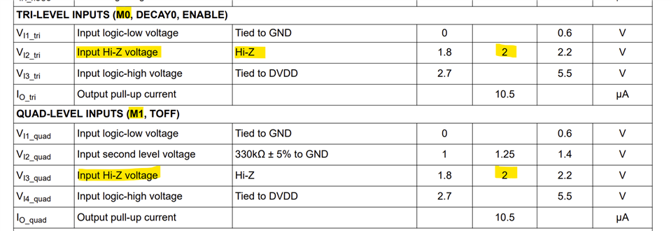
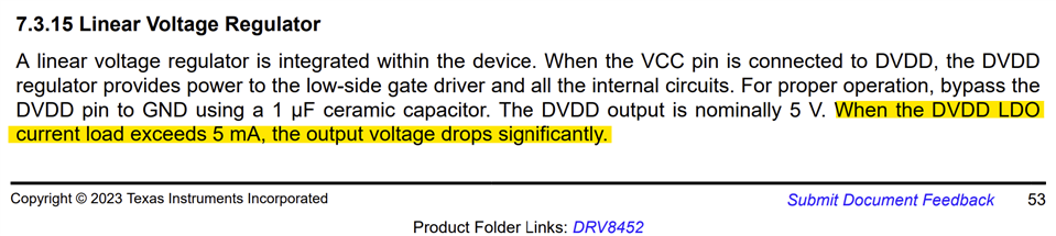
I have measured the voltage in pins of DRV8452 directly, and it was correct, if I connected them to DVDD or GND, there was 5V and 0V respectively.
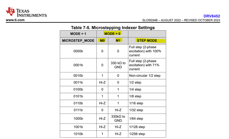
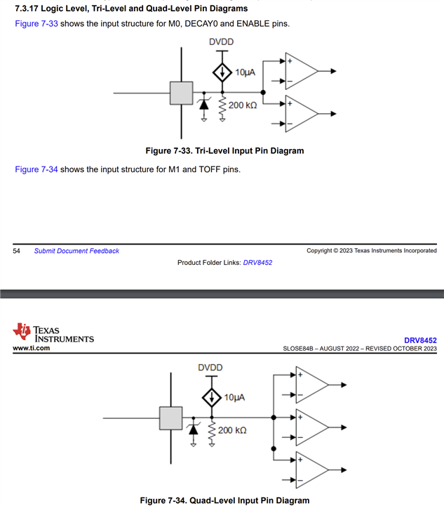
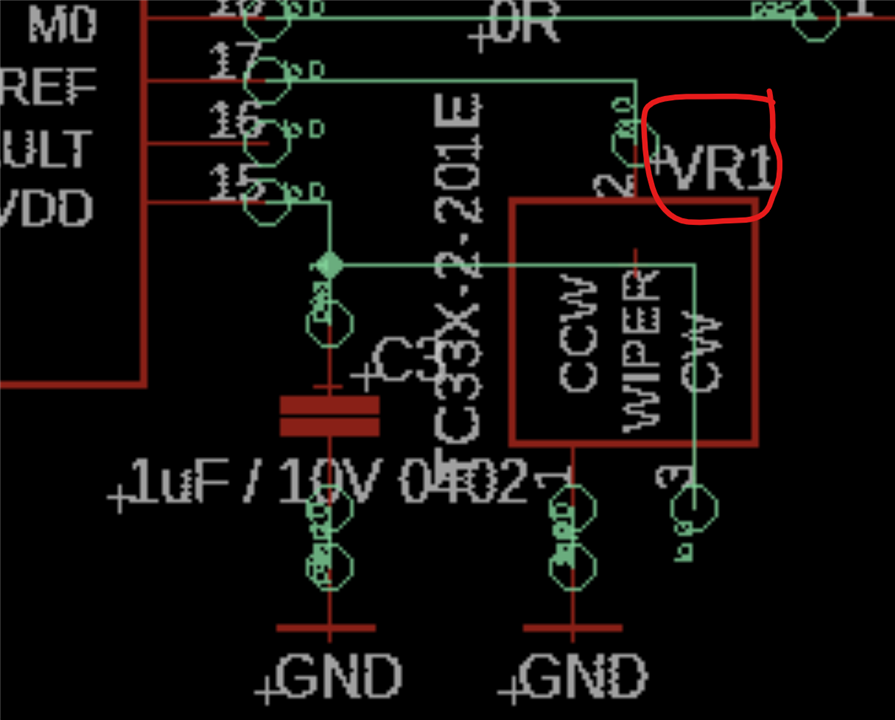
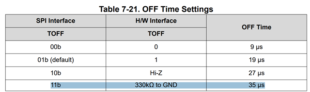
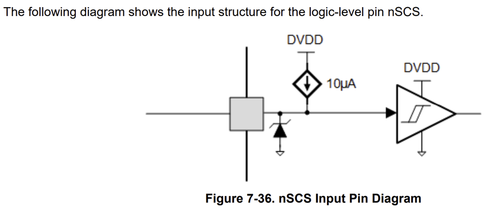
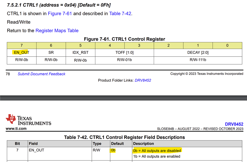
In datasheet I found this:

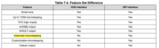
So HWinterface supports microstepping, do I have to enable it somehow?

Thank you for helping me.
Have a great day

Ondra

  • Hi Ondra,

    While using HW interface for the DRV8452 microstepping is set with M0 and M1 pins. Auto microstepping (interpolation) feature is available via SPI only. Please see below for M0 and M1 setting table from the datasheet.

    Regards, Murugavel

  • Hi Murugavel, 

    Im familiar with the table you send in reply, correct me if Im wrong, since I have PWP package and  HW-interface,
    there is not MODE pin, so i dont care about its state.

    When I tried to set some microstepping, for example (as it was the easiest for me, since the schematic is as is..) I leave both M0 and M1 unconnected = Hi-Z
    (is it correct?) I understand Hi-Z as Hi imedance - so its open circuit.. unconnected...   
    Nothing changed...  It still went like one pulse =one step of motor

    I tried to connect "1"  so DVDD, and on pis was 5.0V  and  nothing changed...
    It still went like one pulse =one step of motor

    I know, my schematic is simple, but is it correct?

    There are no protections, no isolation...
    I just wanted to test this driver on signal generator, If it fits my case and than I would make much better circuitry around the IC.
    While testing it, I set lets say 10Hz on signal generator.

    If schematic is correct, lets find what could cause this.. I double checked my soldering          (I measured what is supposed to be on pins)
    Is there any possibility ESD damage could cause this?      (I have ESD safe soldering iron, even hot-air, I used it there)
    Shoulůd I try another IC?          (is there any chance this one is faulty?)

    Thank you for reply
    Have a great day

    BRs

    Ondra

  • Hi Ondra,

    You're correct with PWP package there is no MODE pin and the DRV8452PWPR orderable device will be a fixed HW mode option. For this device if M0 and M1 are left floating (Hi-Z) we expect the device to be in 1/128 uStep mode. I don't see anything unusual with the schematic. You can measure the voltage on M0 and M1 to make sure they are in compliance with the datasheet and verify they are in truly the expected mode.

    If these check out okay it will be a good idea to replace the device and test again. Sorry you are facing this issue. I have not tested the DRV8452 but I have tested the DRV8462 in HW mode and seen it work as expected for microstep settings. DRV8452 should behave similar. 

    Could you please capture the current waveform with this current IC for either A phase or B phase coils?  

    Regards, Murugavel 

  • Hi Murugavel,

    thank you for that table, I have seen it before, but maybe didnt give it as much attention as I should...
    I will measure current of one of the motor coils, but in maybe 1/2 days, so I will let you know there.

    One thing I remember when I was troubleshooting with that driver, was that actually, when I left the M0 or M1 in Hi-Z,
    I was able to measure there only cca 1.6mV, that surprised me, but now, when I have my eyes on that table again, I see a problem there.

    Another thing is, when I connected there DVDD or GND, I measured 5V and 0.0mV respectively, (looks like pins are internally not connected? but then why the logic stays on logic zeros on both, and goes 1/1microstepping?) I dont know..

    Thank you 
    Have a great day

    BRs
    Ondra

  • Hi Ondra,

    These pins have high input resistance, you can see a low constant current source and a 200 kΩ pulldown resistor on them. You're correct when it is close to 0 V on M0 and M1, FS 100% IFS is selected. 


    I think I may have caught the issue on your PCB. What is the value of the VR1? If I read correctly, TC33X-2-201E is a 200 Ω potentiometer. This is severely loading the DVDD output. 5/200 = 25 mA. The internal LDO can deliver just a few mA and not intended for external loads other than pullups (≥ 10 kΩ) and properly sized VREF potential divider again ≥ 10 kΩ, I'd suggest a 22 or 47 kΩ potentiometer. DVDD must measure 5 V (assuming VM = 24V) for proper operation of the device. Please change this potentiometer. I think this will fix the issue for you.


    Regards, Murugavel

  • Hi Murugavel,

    You are correct, the potentiometer in schematic would be wrong, but I used this one just because of the package, I has some simillar looking variable resistor here so I used it insted of the one in schematic, again, it was just because of pad layout. In reality, on this place is 20kOhm potentiometer
    even the current can be set without a problem.  (DVDD is very stable and precisely holding on 5.02V)   

    I have here some images of current on one of the coils:
    first image is with 0.1 Ohm resistor in series with the coil,                                    and the second image is with 47Ohm power resistor:


    I will now solder on the place new IC and will let you know if it behaved the same way, or if there will be some improvement.

    Thank you and have a nice day
    BRs,

    Ondra

  • Im really sorry for that mistake in schematic.
    Schematic should be clear.. I know
    Im sorry for that..

  • Hi again Murugavel,


    I have tested new IC now and sadly, it behaved the same way as the one before.

    I unsoldered the potentiometer and nothing changed, but than I was just measuring around, I found some Interesting (at least for me) fact, 
    that is.. when I left M0 floating, I measured 4.93V there! I believe there should be something around 2V. (if left floating)

    I didnt know where from it came there, but (since it is M0 pin) I tried to short it to ground, and my powersupply has shown around 30mA increase in current, motor was not spinning, just holding and current was left floating (i know it is not good idea), powersupply shown nearly zero, so there was not set current in to coils of motor.

    Since I ordered these ICs as a samples, the marking is a little different and I wonder if someone just didnt marked this chip only as in general DRV8452 
    Simply said: my idea is, that this IC is actually SPI version...

    What do you think about it? could this be real?
    It is just idea, because I dont see why it doesnt work...

    Thank you and have a great day

    BRs
    Ondra 

  • Hi Ondra,

    No worries about the schematic issue. I thought that was the issue. I guess it is not as simple as I thought the problem to be.

    Regards, Murugavel

  • There is one more small change not in schematic and thats around TOFF pin:

    I have there 330K to GND resistor (in schematic there is 0R...)

    I would try something in order to figure it out, but I dont have an idea what can I try..
    Thank you Murugavel, and have a nice day.

    BRs
    Ondra

  • Hi Ondra,

    Sorry to hear changing the issue did not resolve your issue. Are the IC marked DRV8452? No "S" suffix and on the shipping box as well? Your observation of 5V on M0 pin is mysterious considering an "S" device. See below. The SCLK and nSCS are inputs. Vcc pin sets the logic high level output at SDO pin for the S device. In the H device that's TOFF which is connected to GND in your schematic, so no chance of an SDO output which could be connected to GND because you have DECAY1 to GND.

    Can we do another experiment? Try lifting up the M0 and M1 pins from the PCB and leave them floating and perform a test. If the M0 still measures 5V and have same behavior please stop all further tests. We'll sample a DRV8452H device and try to reproduce the functionality of M0 and M1. Sorry this debug is taking longer than we'd like it to.

    Regards, Murugavel

  • Hi Ondra,

    Just pushed the reply button. But 330k to GND rules out any grounding of a potential SDO pin. If you could isolate M0 and M1 that will definitely let us know what is going on. Thank you.

    Regards, Murugavel

  • Hi Murugavel,
    Just measured it and I wanna say: Only SJ3 in my schematic is shorted, others I left floating.

    On M0 pin was still 4.93V  (same as DVDD)  
    On DECAY0 and M1 was something around 0.7mV and 1.3mV respectively.


    So what would you say? does it correspond to SPI device?

    Thank you

    BRs
    Ondra

  • There are some photos:       these are samples, so their marking can differ from normal ICs


  • Hi Ondra,

    If M0 measures 5 V same as VDD I have a strong suspicion it may be the nSCS pin of the SPI device. However the unexpected behavior is what you observed when shorting that pin to GND. It should not load the DVDD because the pin is biased from a weak current source. That indicates some other possible failure.

    Thank you for the images of the device. I'll verify with the database. Meanwhile I'm going to sample some DRV8452PWP devices and test in our lab. Thank you very much for your patience.

    Regards, Murugavel

  • Hi Murugavel, 

    To the behavior when I shorted M0 pin to GND,  since in that time VREF was floating, and VREF is next to the M0 pin,
    I think that could be the source of that behavior, it inducet something on VREF - than current to the motor coils changed..

    I dont know if it was reason, but I think, it could be..  
    Thank you for your time today, I think, we moved a bit closer to the solution Smiley

    Maybe,I will try to connect some MCU and try to communicate over SPI tomorrow.
    Have a great day

    BRs
    Ondra

  • Hi Ondra,

    Thanks for the additional info. VREF to GND should not cause this behavior. That'll make the coil current close to 0. Anyways an M0 pin not reading 2V is suspicious. From that standpoint we know what the issue is regarding microstep setting. But another unsettling issue is even if we assume SPI device the default microstep mode is not full-step mode. It should be 1/16. So I'd not want you to waste trying an SPI communication. Two devices damaged back to back while handling has a very low likelihood, but I've seen it happen.  

    And also the output H-bridges would be disabled by default. 

    I've placed orders for DRV8452PWP samples. I should be able to reproduce the issue by early next week. Please bear with us for the delay this is causing debugging this issue. Thanks and have a nice day! 

    Regards, Murugavel

  • Hi Murugavel, 
    Do you have something new about samples of DRV8452?
    Thank you

    BRs
    Ondra

  • Hi Ondra,

    I received the new samples yesterday. I am in the process of getting it soldered to one of the DRV8434EVMs that has a PWP package. I'll know the outcome within the next couple of days, latest by early next week. Thanks for following up.

    Regards, Murugavel

  • Hi Ondra,

    I received the reworked DRV8434EVM with a DRV8452 device, https://www.ti.com/tool/DRV8434EVM sooner than I expected. We used a NEMA17 stepper connected to the EVM with 1A IFS, 24 V with this GUI,  https://dev.ti.com/gallery/view/MotorDriversBSM/DRV84xx/ver/0.1.4/. Got it set up, set VREF to 1.32V (=1A IFS) using the GUI, VM 24V.  We were able to change between all microstep settings and had it work as we expected it to, no issues. 

    We also tested through all decay modes and all TOFF settings, all worked as expected. Changing step mode no matter what the decay mode and TOFF settings were, the device worked as expected with proper microstep modes.

    The schematic and Altium project files of the DRV8434EVM can be downloaded from the EVM webpage, https://dr-download.ti.com/design-tools-simulation/design-tool/MD-K8lGuBogFK/01.00.00.0B/sloc356b.zip

    I also verified the factory code on the device image you shared in your post. They checked out to be correct DRV8452 hardware version devices. 

    This only adds more to the mystery of the issue you were seeing, unfortunately. Perhaps you can double check your hardware one more time and as a contingency backup order a new set of the DRV8452PWP samples for further testing. Having a DRV8434EVM would be helpful but not really necessary. 

    Regards, Murugavel


  • Hi Murugavel,
    I have done some work around DRV8452, I have tested it again but nothing changed..
    Since I dont have the EVM board, I would like to do some test before I buy the board, because than I dont see any choice...

    Could you please set the driver according to this configuration:   ?

    TOFF: 35uS - 330K to GND     (Current Ripple: 25mA + 6% Itrip)

    Mixed decay: 60% fast:
    DECAY0: Hi-Z
    DECAY1: 0 (GND)

    Microstepping 1/128:
    M0: Hi-Z
    M1: Hi-Z


    Than please measure voltage over all pins in J3 on your EVM board (I mean the main header whre you can measure voltages on DRV8452 pads).
    I will use it as refference and i will set DRV8452 the same,and we should probably see some difference between your values and mine.
    I think it could tell us a bit more.

    Please measure also DVDD, which is not on the header, its testpad nearby..

    Could you please verify and share the coil current using an oscilloscope as well?

    If you possess a more effective method for testing and comparing these without physically handling both of them, please share your insights.

    BRs

    Ondra

  • Hi Ondra,

    I found a potential issue in your schematic looking at it one more time thoroughly. I think this escaped my attention last time because of the netlist labeling. Usually Vcc netlist label is used for low voltage such as MCU domain 3.3 V or 5 V. VM netlist label is used for the motor power supply, connected to the VM pin-2 and pin-13 of the DRV8452. In your schematic I found VCC used for 24 V motor supply. The nLSEEP pin is also pulled high to this 24 V motor supply VCC. The nSLEEP pin absolute maximum is same as the VM voltage so connecting it to 24 V electrically not affect the pin longevity. All other control pins must not exceed 5.75 V though. 

    I see the nSLEEP is also connected to the MCU control GPIO so this voltage could potentially affect the MCU. Usually we connect the nSLEEP to the same GPIO voltage domain as the MCU for logic HIGH. This is how it is in the EVM. Could you please try removing R1 10k and setting the nSLEEP pin high with the MCU GPIO? Not sure what was the voltage on the nSLEEP pin with this resistor and also pulled high to MCU voltage domain with the GPIO control. 


    If this does not resolve the issue please let me know. I'll try to get the requested measurement information for you by tomorrow my time. 

    Technically speaking you won't have to buy a DRV8434EVM board to make this device work. It should work as described in the datasheet. I hope we can get this resolved soon. Thank you.

    Regards, Murugavel   

  • Hi Murugavel, 
    At first, you hit the right spot, everithing is solved now Smiley
    Since I started to control nSLEEP pin directly with logic voltage, it worked as it should.

    I just would like to say, It was pulled up to VCC, because I hadnt another powersupply on board, so I went through datasheet and I saw it has max voltage VM, so I was thinking its not a problem...   

    Beacause it is meant to be an industrial driver, on prototype I had only 24V and logic inputs from external devices...

    Now I have modified sine wave on coil current as it should be.


    Thank you very much Murugavel, I dont think I would find this issue...

    Since everything is fine now..
    I wanna thank you for your time while helping me Slight smile

    Have a great day

    BRs
    Ondra 

  • Hi Ondra,

    I'm glad the issue was resolved finally. Thank you.

    Regards, Murugavel