This thread has been locked.

If you have a related question, please click the "Ask a related question" button in the top right corner. The newly created question will be automatically linked to this question.

DRV8718S-Q1EVM: DRV8718S-Q1 EVM Development board

Part Number: DRV8718S-Q1EVM
Other Parts Discussed in Thread: DRV8718-Q1,

Hello sir ,

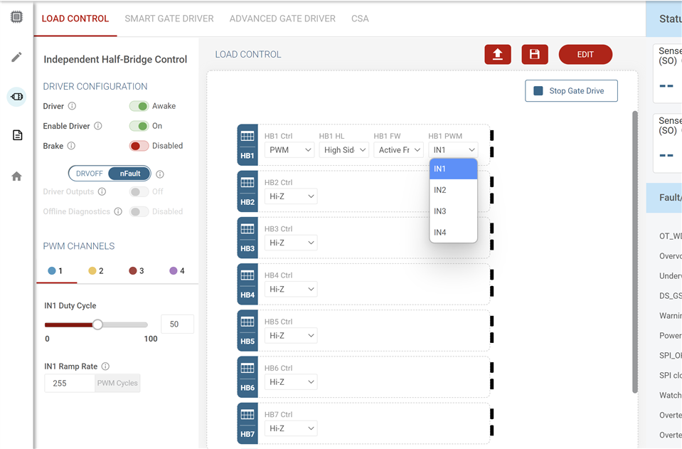
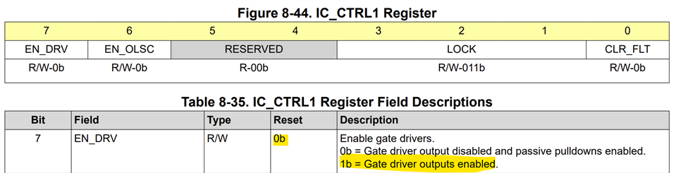
1)I am using  DRV8718-Q1 EVM board , am also changing the PWM value of input but there is no output coming . Please tell me how can i use this EVM board .

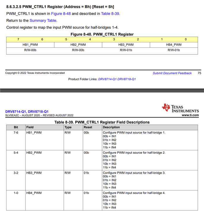
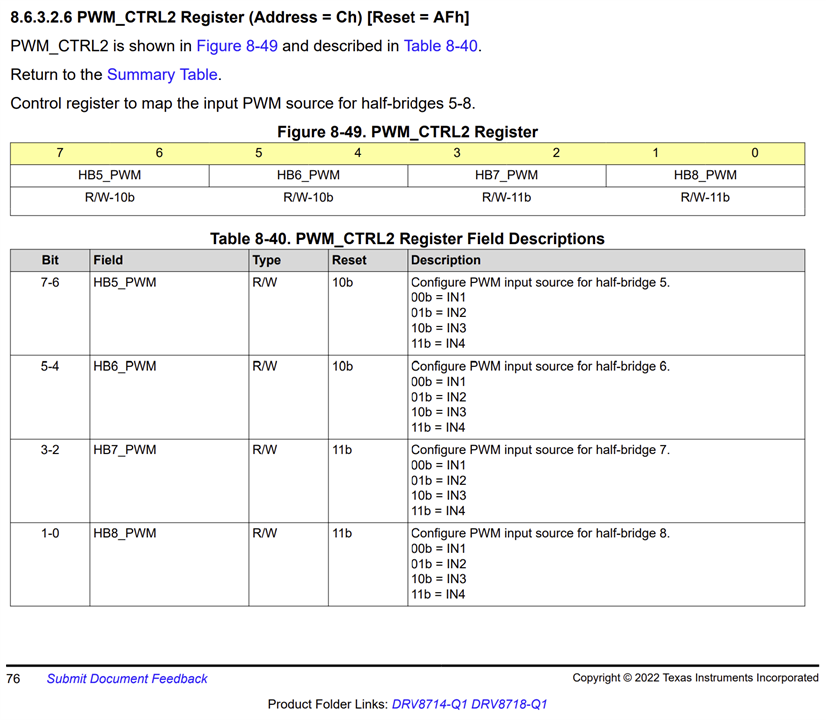
2) There are 8 Output but input is 4 how can it work rest 4 output . 

  • Hello Aryan,

    Have you followed the procedure described in the EVM User's Guide (UG)? The EVM hardware UG is at  https://www.ti.com/lit/ug/slvubn5a/slvubn5a.pdf and the EVM GUI UG is at https://www.ti.com/lit/ug/slvubn6a/slvubn6a.pdf/

    1. Were you able to verify the EVM GUI connected and recognized the DRV8718S-Q1EVM successfully? How were the output loads connected, high side or low side or in H-bridge configuration? I'm assuming you had the Driver in Awake, Enable Driver in On position and DRVOFF / nFault slider in nFault (If in DRVOFF position Driver Outputs must be in On position to enable the outputs. Next according to the load connection you must choose HB1-8 control, HB1-8 High Side or Low Side, HB1-8 Freewheeling and HB1-8 PWM input mapping IN1 to IN4. After this step you can select the corresponding PWM CHANNELS tabs to vary the duty cycle from 0 to 100 %. 

    2. For each of the 8 outputs the inputs IN1 to IN4 can be mapped using the GUI control or the corresponding registers settings in the device using the Register control page of the GUI. See GUI control example below. 

    Register configurations:

    Regards, Murugavel

  • For selecting the particular mosfet output in EVM board . can i set the upside setting  in evm . it is set privously . 

  • should I follow your first point 

  • Hello Aryan,

    If you've connected the load from OUT to GND you must select PWM and Low Side setting. If you've connected the load from OUT to VM you must select PWM and High Side setting. Yes follow the steps described in 1 and 2 to have correct PWM input for the corresponding output channel.

    Regards, Murugavel

  • ok sir it was working through GUI . if i can use external different MCU  for controlling this IC . can i control the output without SPI  giving input IN1, IN2 directlty .

  • Hello Aryan,

    You won't be able to control the output without writing to SPI registers. To enable the driver output the EN_DRV must be 1. Then other configurations may be necessary per your application. You can check the default values of the registers and determine which of them can remain with default values.

    Regards, Murugavel