Other Parts Discussed in Thread: DRV8462
Dear TI experts,
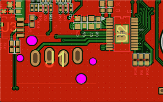
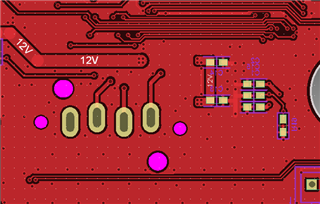
My customer tests DRV8889-Q1 with their own PCB. and there is a heat when motor is operated.
My customer says that the heat is about 60℃. I want to know that this temperature is reasonable when DRV8889 is working.
the condition is as below ;
Vref :3V
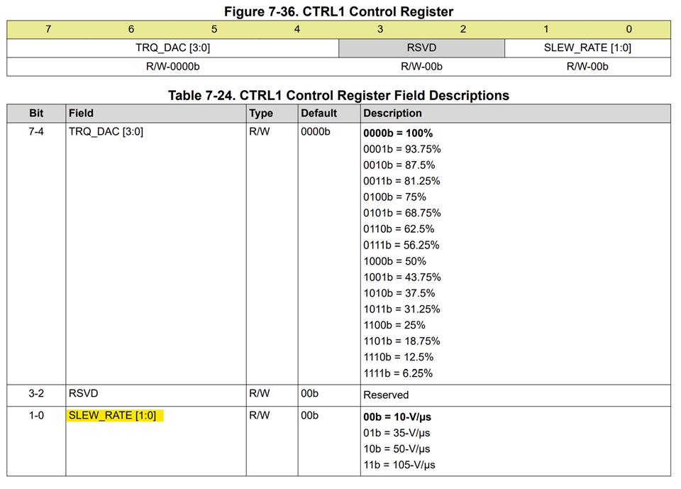
TQA DAC : 62.5%
Current : 0.6A
Step : 1/16
And here are more questions ;
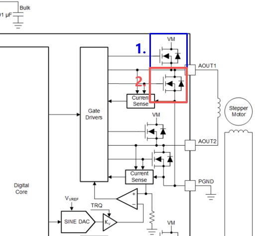
1. Can I turn off no.1 FET and turn on no.2 FET when motor is not rotated?
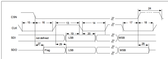
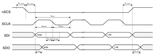
2. I only saw the SPI timing requirements on section 6.6 on the datasheet. Do you have timing diagram chart about SPI timing?
3. I found a register about stall threshold.(STALL_TH)
If I set this value, Can I see stall detection if this value is under STALL_TH?
What should I set STALL_TH if I want to see stall detection even light load? (high STALL_TH or low STALL_TH?)
Best regards,
Chase