This thread has been locked.

If you have a related question, please click the "Ask a related question" button in the top right corner. The newly created question will be automatically linked to this question.

DRV8701: Operation at 15KHz has no power at lower Duty Cycles < 60% Operation > than 5KHz PWM Frequencies = Duty cycle control issues.

Part Number: DRV8701
Other Parts Discussed in Thread: DRV8245-Q1, DRV8462, DRV8234, DRV8962, DRV8214, DRV8262

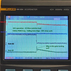
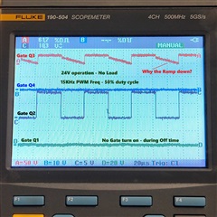
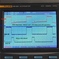
I am trying to replace ST VNH5019 with DRV8701 and External FETs.  Schematic below.  I suspect given these FETs that I should be running iDrive at the 25/50mA.  The VNH5019 had very good response with our motor when running at 15Khz.  We had good low-end control down to 35% duty cycle.  Running the DRV8701 in this configuration (15Khz), the motor would barely move if at all at 50% duty cycle.  If I run the DRV8701 at 1KHz then I get really good control of the DRV8701 down to 20% duty cycle, but then there is the 1Khz audible noise.  At 2KHz and 5KHz duty cycles, control of the motor at low duty cycle falls off.

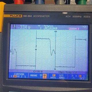
Given this circuit and the same motor as the VNH5019, why does PWM frequency affect the motor control at lower duty cycle from 20 to 75%?  I also have Oscope screen shots at some of the various frequencies.

It has been suggested by some to change the zero ohm resistors R1, R2, R3, R5 to some other value.  But isn't that the point of the iDrive?  Slew rate control.

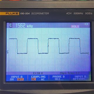
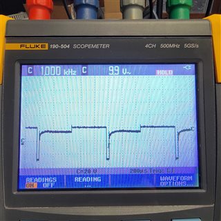
Further, at the very beginning of the OFF period of the two active FETS (one high side and one low side), the other high side FET turns on for some amount of time.  This is more distinct at lower PWM frequencies and looks more like a right triangle

  • One of the main differences I see between the operation of the VHN5019 and the DRV8701 is that the VHN5019 turns on the high side FET continuously, then PWMs the low side FET.  The DRV8701 PWM's the High AND Low side FET.  Is the DRV8701 capable of doing that like the VHN5019?

  • Hi Jason,

    It sounds like you are looking for independent half-bridge control. Unfortunately, the DRV8701 doesn't have an independent half-bridge control mode, only PWM or PH/EN. I would recommend looking at the DRV8702-Q1, which has the same functionality as the DRV8701 but does have independent control mode. Another option would be one of our new gate driver designs, the DRV8706-Q1 which also features independent half-bridge mode and a Split HS and LS Solenoid Control Mode. 

    Best,

    David

  • Update:  When I measure Vgs of Q1 I don't see the rise on the gate like I do when measuring from the gate of Q1 to GND.  Q4 is off, so Q1 can't really turn on.

    All of these measurements are in a single direction to keep things simple.  The attached scope plots are measured WRT GND.  PWM_MotorUpperPiston is 15.625KHz PWM signal. UpperPistonINA and UpperPistonINB are static direction signals.  

    Assumption:  I am assuming that this driver IC needs PWM on IN1 and IN2 is low for one direction and PWM on IN2 and IN1 is low for the other direction.

    Question: Could it be operating poorly because the FETs are Vgs = 16V and Vds=40V?

  • Hi Jason,

    I will try to recreate this issue in the lab tomorrow and will let you know what I find.

    Best,

    David

  • HI David,

    Thank you for the response, but I don't see how independent half-bridge interface helps. 

    It looks like from this table that if IN1/PH is 0 or 1 then IN2/EN is a don't care and I can't drive GH2 or GL2.  Hopefully, I'm just interpreting this table wrong.


    The end goal here is to be able to drive a single Brushed DC motor in two directions with PWM >= 15KHz.   Is the DRV8701 suited for that or not?

    Is there a way we can talk in real time over a phone call or video chat?

  • Hi Jason,

    Do these issues still occur when IDRIVE is increased? 

    Please see the attached application note on Understanding Smart Gate Drive to better understand the gate current and frequency relationship.

    Use the calculation below to calculate the required gate current. 

    If you don't already I would suggest testing on one of our Evaluation Modules (DRV8701EVM)  for easy design testing. 

    Best,

    David

  • Hi David,

    I put 68K to AVDD (strongest drive strength) and the problem still exists.  The rise time in this mode is 140ns.  With IDrive floating, I get a rise time of 202ns.  Of course, I also don't have an active probe so there's also a 10pF load for the probe so this is likely slowing down the signal somewhat.  I had already worked the calculations for IDrive.  For these FETs (Infineon PN: IAUC100N04S6L025)  the total gate charge is 25nC and 5.1nC Qgd.  Given these calculations at 15.625KHz my IDrive should be in the 34 to 51mA range.  A source and sink of 100/200 should yield 51ns rise and 26ns fall.  Again, I'm not sure what the /true/ rise time is since my scope probe has 10pF load.

    I'm still at a loss as to why, given the same motor, same PWM frequency, different drivers (DRV8701 and VNH5019) yield vastly different results even though the motor waveforms are comparable.

  • Hi Jason,

    Please allow 24 hours for me to discuss these issues with my team and I will get back as soon as I know more. 

    Best,

    David

  • Hi David,

    After conversing with a long time mentor of mine, I have found the reason why the motor is behaving in this strange manner.  The issue is that PWM on IN1 while IN2 is low, controls the gate to GH1 and GL2.  The fact that both are turning on/off at the same time shows a motor waveform like the following.

    This is a scope shot taken at the terminals of the DC motor running at 15KHz PWM 50% duty cycle.  You'll notice that there is a positive and an almost equal  negative component.  If you take the RMS of this, you'll see that there is enough to move the motor slowly in the negative direction based on how the scope terminals are connected.

    Conversely, The VNH5019, shows zero negative voltage as shown below.

    The RMS of this is very positive (based on how the scope probe is connected) and allows the motor to run at roughly 50% power.

    The reason the DRV8701 works better at lower frequencies is simply the on time of the positive pulse, but also that the short time of the negative pulse  which "recovers" significantly over the extra time between pulses.   This allows the RMS of the waveform to be more positive as shown in the scope capture below at 1KHz PWM 50% duty cycle.  You can see a negative shoot, but you also see a long recovery.  The RMS of this waveform is about 10V.

    That said, this part will not work for my application.  You were right, I need 2 independent half bridges to accomplish what I need.  I need to be able to hold either the high or low side steady, and PWM the other side.  This is the only way to get the RMS offset I need to drive this motor correctly.

  • Hi Jason,

    Thanks for your update, and I'm happy to hear that you have found the cause of your issue. 

    Sorry to hear the DRV8701 won't be a good fit for your application, but as I said before please look into some of our newer gate drivers and high current integrated drivers for this or other future applications.

    Integrated Drivers:

    The DRV8245-Q1 has an absolute maximum voltage up to 40 V with a peak output current of 32 A. The device can be configured as a single full-bridge driver or as two independent half-bridge drivers. 

    Link: DRV8245-Q1 - Automotive 40 V, 32 A H-Bridge driver with integrated current sensing and feedback 

    Gate Drivers:

    The DRV8706-Q1 has many updated and advanced features, one of which is independent half-bridge mode. 

    Best,

    David

  • Hello Jason,

    Thank you all for your time today. Like we discussed the PWM mode speed control requires a specific control logic. Please see below control table from the datasheet. For proper PWM speed control the motor current must be recirculated with slow decay during the off time of the bridge HS-FET that was driving the motor in a specific direction. To achieve slow decay via the LS-FETs both IN1 and IN2 must be logic HIGH while this device is used in PWM control interface option - DRV8701P. A logic LOW PWM on any of the inputs would actively drive the motor (this may be the off time of the PWM input). During this drive the other pin must be logic HIGH. A logic HIGH PWM would then allow the recirculation current through LS-FETs decaying the current.

    If this control logic is not followed, for example letting the motor to coast by making both inputs LOW and driving by making one of the inputs HIGH with a PWM the coil current would not decay fast enough for proper speed regulation. I hope this information helps you to correctly configure the DRV8701P for proper PWM control. 

    Thank you for your feedback for improving the description in the datasheet.   

    Regards, Murugavel

  • Thank you for this!  I have changed the dual AND gate for a dual NAND gate, but this changed the "direction".  So a quick software change later, and all is well.  This works VERY well at 15KHz and I now have no issues.   Admittedly, I would have thought that "coast" would be the right answer during the PWM "off time" however, I can see now this isn't the case.   While not intuitive, I can't argue with the results of using "slow decay (brake)" during the PWM "off time".  The driver works well in this mode and I am very pleased with the outcome.  Thank you again for your help and insight in this.

    Warmest Regards,

    Jason

  • Hi Jason,

    Happy to hear you were able to address the hardware changes without spinning the PCB by using a dual AND gate and using firmware to change the direction. I'm glad your application works very well at 15kHz with the DRV8701. Thank you for the update and your kind feedback, much appreciated. 

    Please feel free to contact us via E2E for your future motor drive requirements. We have several new devices in our integrated motor drive portfolio, for example the recently products DRV8245-Q1, DRV8262, DRV8962 and also DRV8214, DRV8234 that have integrated sensor less electronic encoder for BDC motors that leverages the current ripples generated at the commutator. We are working on a few new devices as we speak including stepper motor drivers such as the DRV8462.

    Regards, Murugavel