This thread has been locked.

If you have a related question, please click the "Ask a related question" button in the top right corner. The newly created question will be automatically linked to this question.

DRV8262EVM: Driving TEC

Part Number: DRV8262EVM
Other Parts Discussed in Thread: DRV8262,

Hello,

I am trying to use the DRV8262 to drive a TEC but I am having issues with the integrated current regulation, and was hoping someone might have an insight. 

I have an LC filter (same as DRV8262 datasheet) at each leg of the TEC, with L=22uH and C = 20uF. The nominal resistance of TEC = 2ohm. Input voltage is 12V

DRV8262 configuration:

Toff=7us

Decay mode = slow

Dual Hbridge mode (using output 1/2)

I am specifically trying to use the integrated current regulation by adjusting Vref and inputting a ON/OFF signal (100% duty cycle only). 

Observations:

If Vref is high enough (>0.7V), pushing the current past ~1.2A, the current starts to oscillate(>50% ripples) wildly, looks like unstable current regulation loop. The higher I push Vref, the larger the current oscillations get. 

If Vref is lower than .7V, current is stable but lowering Vref does not lower the current through the TEC, even at Vref = 0.

If I use input duty cycle(@200kHz) to adjust current, output current looks good (low ripple), and current level follows duty cycle.

Am I missing something on how the integrated current regulation works? Is there something I am missing specific to the EVM?  Any suggestions?

elembio_DRV8262EVM_test.zip

  • Hi Alan,

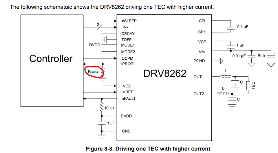
    What was the value of the RIPROPI used in your testing - was it the default values in the EVM? You said single H-bridge mode I assume both bridges were connected in parallel, correct? Assuming parallel connected H-bridges did you connect the two, IPROPI1 and 2 with the jumper short? 

    Regards, Murugavel

  • Hi Murugavel,

    I apologize, but I meant to say I am using a single Hbridge in dual hbridge mode (corrected my post to reflect this). So I am not using those jumpers you indicated. 

    I using the default Riprop value of 3.3kohms.

  • Hi Alan,

    No worries I probably misunderstood. Thanks for the clarification. Can you measure the VREF voltage and found it to be the expected value on the VREF pin? If you could capture the current waveform it may be helpful to debug what is going on. You could capture the IPROPI waveform if you do not have a non contact current probe. 

    Regards, Murugavel

  • Hi Murugavel,

    I have attached to the original post the oscope screen captures of the current waveform with a non contact probe. 

    Images are numbered in the sequence of the tests performed. The test involved changing vref in the following order: 0.5V, 0.4V, 0.3V, 0.0V, 0.6V, 0.61V, 0.65V

    Note that the 0.61V and 0.65V captures have different scaling.

    I also confirmed the different vref voltages at the IC pin with a multimeter.

    As you can see, VREF in the range from 0.6V to 0V does not regulate the output current.

    Just changing VREF from .6 to .61, introduces significant instabilities to the current waveform and .65V just makes them worse.

    I also measured the voltage at the iprop1 pin and its around .6V, which is also expected based on RMS current of 0.9A, 3.3K resistor and 212uA/A gain.

  • Hi Alan,

    Sorry I did not notice that. Let me look into it and get back to you.

    Regards, Murugavel

  • Hi Alan,

    I plan to reproduce this issue with one of the DRV8262EVMs. I'll keep you posted.

    Regards, Murugavel

  • Great, looking forward to your results!

  • Hi Alan,

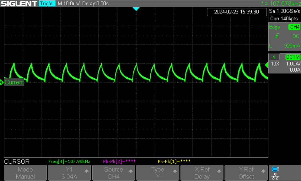
    I tried to reproduce the current regulation with a 8Ω resistive load and 12 V VM supply voltage. While trying to set to slow decay I found there was an issue with the GUI. The option for slow decay setting was missing. See below. I have noted this issue and added to the list of items to be addressed in the next revision. 

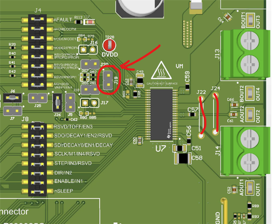
    Meanwhile, I manually configured the DECAY pin to slow decay by connecting it to GND. Had to remove a jumper short and connect the header pin for DECAY to GND. See below. In your initial post you mentioned you set slow decay. How did you set it? 

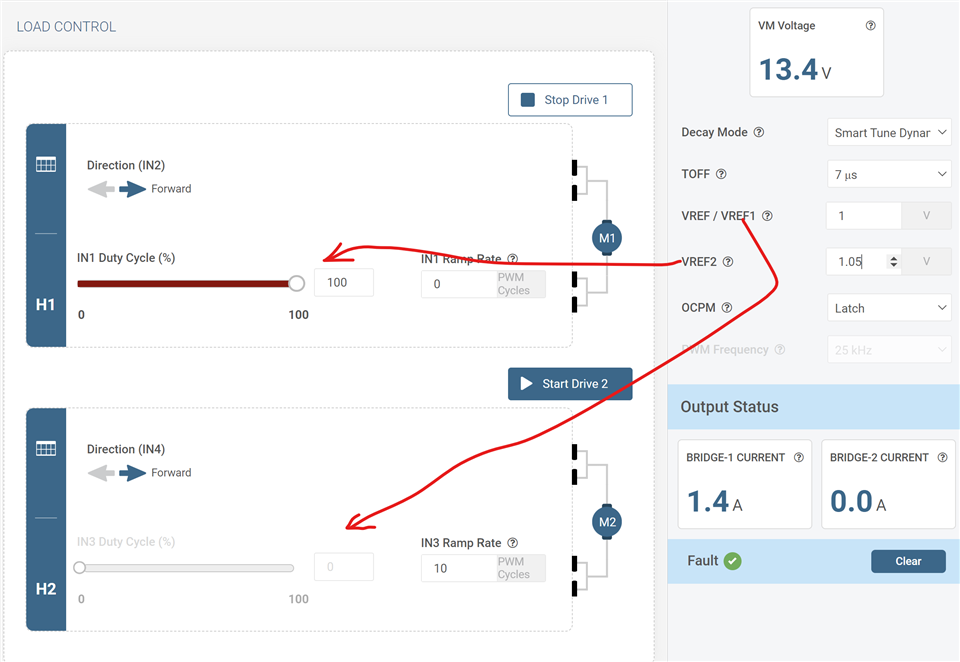
    I set TOFF to 7 us. I also set the IN! ramp rate to 0 for immediate ramp to 100 % duty cycle to set IN1 to HIGH. I also found in the GUI VREF2 controlled H-1 and VREF1 controlled H-2. This issue was also added to the previous list for GUI revision. 

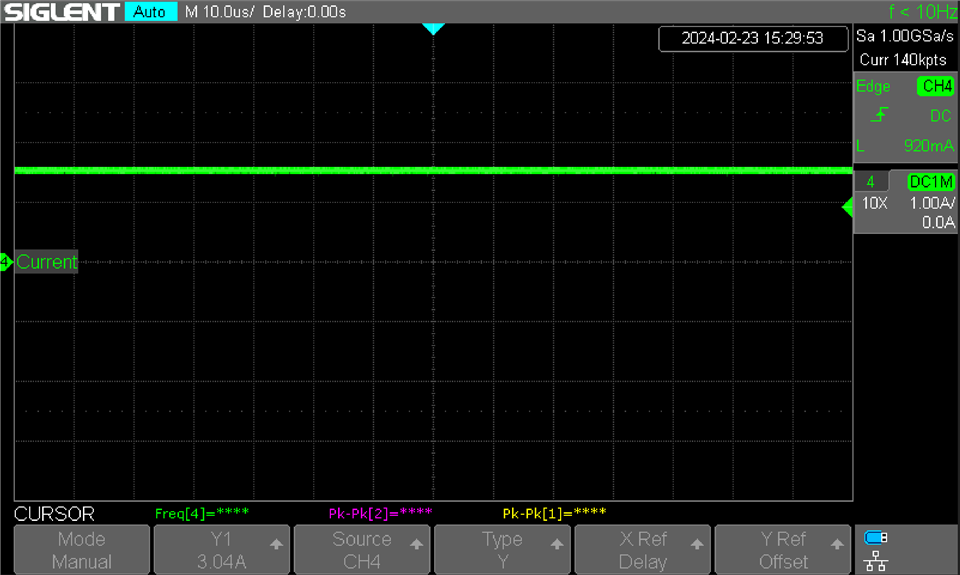
    At around 1.05V VREF there was no current regulation because the target current was > 12/8 =  1.5 A. The GUI read 1.4 A and the scope capture as below using a non-contact DC current probe.

    Next I set the VREF to 0.75 A by setting VREF = 0.52 V. The GUI read 0.7 A average current. See below, the corresponding scope capture. 

    After this, I set the VREF to 0.375 A by setting VREF = 0.26 V. The GUI read 0.3 A average current. See below, the corresponding scope capture.   

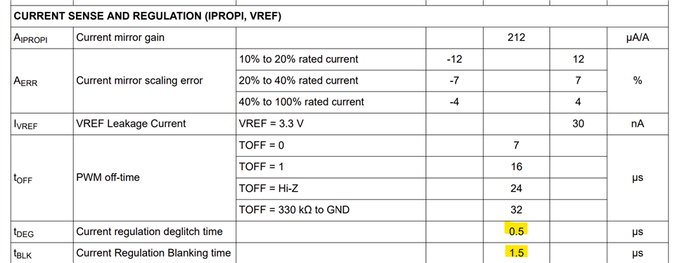
    Then I set the VREF to 0.1875 A by setting VREF = 0.13 V. The GUI still read 0.3 A average current and no change with the scope capture waveform. The duty cycle will not reduce below this value. This is because of the tBLANK time. See below info from the datasheet. This will limit the lower end of the current regulation level.

    The EVM RIPROPI is 3.3 kΩ to support 5 A full scale current setting. You can increase the value of RIPROPI such that scaled full-scale current corresponds to 3.3 V VREF input voltage. This will give a better range. I think the issue you were seeing could be because of DECAY setting. Please try with the DECAY pin connected to GND. As well as resizing the RIPROPI. Thanks.

    Regards, Murugavel

  • Hi Murugavel,

    I had already noticed the "no option for slow decay" in the GUI, but I forgot to mention. I actually used the exact same jumper location to GND as you :). So all the data I provided is with the hardwired slow decay.

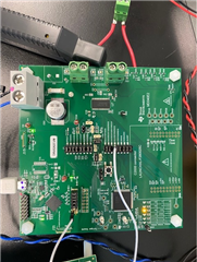
    This is my set up. Please let me know if any of the jumpers dont look right.

    In regards to VREF GUI bug. I cannot reproduce that on my end. I can correctly measure VREF1 at pin 34 of the IC and follows the GUI values. I also confirmed VREF2 in pin 33. 

    Did you use an LC filter for you resistive load? (doesnt seem like it based on your current traces).

    I think the blank time explains the lower end of the regulation current issue.  

    My main issue is how the current regulation becomes wildly unstable just by changing vref from .6 to .61. (maybe this has to do my LC value selection)?

  • Hi Alan,

    I may have had the older revision of the EVM HW with me that had the VREF connections swapped. Thanks for confirming correct operation of this. I recall that was fixed with a later revision of the HW.

    Glad you caught the slow decay issue already. I did not use the LC filter because I do not have those components around especially high current inductor of that value. I did notice the current regulation became unstable with the other two decay modes exactly like you described. After changing to slow decay I did not see those issues. 

    Thanks for the image of your set up. Looks okay to me. The EVM UG also has the images of the EVMs with jumpers in its Appendix section just FYI, https://www.ti.com/lit/pdf/slou558.

    The issue could be due to LC value selection or could be noisy VIPROPI. How does the VIPROPI waveform look? You can use a filter capacitor such as 100 nF across it to smooth the VIPROPI and stabilize the current regulation. I think proper RIPROPI range scaling would also help with stable operation.

    Regards, Murugavel

  • I am using firmware firmware 1.0 per GUI read out.

    I had the same thought as you and have already added 100nF cap across VIPROP but that didn't seem to have an impact.

    I will measure VIPROP, adjust LC values and adjust RIPROP. I will report on this early next week.

    Thanks!

  • Hi Alan,

    The latest GUI is v1.0.3 and firmware 1.01. You can do a firmware update using the File > Program Device option in the GUI. It may or may not make a difference. In my testing I used the v1.01 firmware.

    Regards, Murugavel

  • Hi Murugavel,

    So this week I tried multiple LC configurations, I even went as high as 100uH and 47uF and I am still getting the weird peaking/instability when the internal current regulation kicks in (above  vref=0.6V).

    At this point I think I am misunderstanding how the internal current regulation it works. My understanding is that the current regulation signal will look like a PWM signal with a minimum on time of 1.5us (blank time) and off time of 7us (toff), so a LC filter centered around 10Khz should be enough to keep ripples below 10%. I expect the current to look like figure 7-5 in the datasheet, if my input duty cycle is 100% and I let the internal current regulation + vref level do the work. But no matter what LC values I use, I still get ripples >50% as soon as current regulation is engaged.

    If I PWM input at 100Khz with 10% to 90% cycle I can control the RMS current reliably with <10% ripple at a fixed Vref. So I dont think this issue is related to the LC filter.

  • Hi Alan,

    Thanks for the update. Sorry you were still unable to resolve the issue. We will try to procure some inductors and try to reproduce this behavior next week. 

    Regards, Murugavel

  • Hi Alan,

    I received the inductors and got a chance to verify with 33uH and 22uF L and C on both OUT1 and OUT2 connected to a 12V TEC load. I found that slow decay was causing the issue resulting with not proper current regulation. Using Mixed Decay setting did the trick. Could be the inductor saturated in slow decay mode. I have not investigated this aspect much. The internal current regulation worked as expected.

    Personally I'd prefer not to use this option if you want low ripple with the TEC current. The reason why I say this is, the internal current regulation is fixed tOFF but variable tON. As the target current increases tON becomes longer and the PWM frequency decreases with increasing duty cycle, down to 5 kHz. This is very specific to the current regulation scheme with fixed tOFF variable frequency in the DRV8262. A fixed frequency PWM would be a better fit for this application. The DRV8262 is designed for brushed motor control. Using this driver for TEC is an added benefit especially with higher frequency PWM input support. 

    See results: DRV8262_TEC_Internal_VREG.xlsx

    Because of low PWM frequency the ripple is pronounced. Most TECs tolerate this ripple pretty well, but not ideal. This application note is a good resource on this topic, https://www.ti.com/lit/an/slua979a/slua979a.pdf, Driving a Peltier Element (TEC): Efficiency and Aging. 

    With 100 kHz external PWM input you can have very low ripple with the TEC current for the same LC circuit and if you could regulate this using an external MCU by reading the IPROPI with an ADC input you could have a nice TEC current regulation system with very low current ripple. the DRV8262 can support up to 200 kHz PWM input. 

    I hope this information will be helpful to you. Thank you.

    Regards, Murugavel

  • Hi Murugavel,

    I really appreciate the detailed response!

    What I wanted to achieve is to use the driver as a voltage controlled current source. I wanted the ability to close the TEC temperature control loop with current instead of PWM duty cycle. Granted we can still do this as you mentioned but it would involve reading the current and adding another layer to the overall control loop.

    This has been very insightful and I will continue to explore some options.

    Regards,

    Alan

  • Hi Alan,

    This should work well if you limit the range of operation for closed loop current control. I hope this works for you. Thanks.

    Regards, Murugavel