We are planning to use High current MOSFET.
Below mentioned our requirement follow this,
1. DC continuous 120A
2.VGS = 9V
3.Low RDSon Example(1mohm to 3mohm)
4.Low input and output capacitance
5.VDSS:80V
This thread has been locked.
If you have a related question, please click the "Ask a related question" button in the top right corner. The newly created question will be automatically linked to this question.
We are planning to use High current MOSFET.
Below mentioned our requirement follow this,
1. DC continuous 120A
2.VGS = 9V
3.Low RDSon Example(1mohm to 3mohm)
4.Low input and output capacitance
5.VDSS:80V
Hello Prema,
Thanks for your interest in TI FETs. Our lowest on resistance 80V FET is the CSD19506KTT in D2PAK. Max rds(on) = 2.3mΩ at VGS = 10V. In a 5x6mm SON package, we have the CSD19502Q5B, 4.1mΩ max at VGS = 10V. Please let me know if you have any questions.
Best Regards,
John Wallace
TI FET Applications
Hi john,
thanks for your reply.
we need DC continuous 180A and Ciss capacitance 1000pf and output capacitance Coss less than .>300pf.
prema perumal
Robert Bosch GmbH
Hi Prema,
Thanks for the updated information. This high current requires a FET with very low Rds(on). Die size is inversely proportional to on resistance: lower on resistance = bigger die size and equates to larger input and output capacitance for the FET. TI does not have any FETs that can meet your current requirements with Ciss < 1000pF and Coss < 300pF. For example, the CSD19502Q5B has Ciss = 3570pF typical and Coss = 925pF which exceeds your requirements. In order to support 180A continuous, you would need to parallel 6 x CSD19502Q5B FETs. Ciss and Coss are multiplied by the number of parallel FETs which far exceeds your capacitance limits. Let me know what else I can do to assist you.
Thanks,
John
Hi john,
thanks for your input..
i need some clarification from input below mentioned that point.
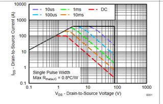
how to relate below attached graph to (In order to support 180A continuous, you would need to parallel 6 x CSD19502Q5B FETs) in this point

Hi Prema,
My recommendation for paralleling 6 FETs is based on the calculated conduction (I² x Rds(on)) loss. I rechecked my analysis and I was mistaken about the number of parallel FETs required. If you use the lowest on resistance FET, CSD19506KTT, I would recommend 6 FETs in parallel (30A/FET) which equates to about 2.64W/FET. This package can dissipate a max of about 4W. If you use the CSD19502Q5B, then I would recommend 8 - 10 FETs in parallel. With 8 FETs (22.5A/FET) the eatimated power loss per FET is about 2.85W. With 10 FETs (18A/FET) the power loss is 1.82W/FET. This package is capable of about 3W maximum power dissipation. What is your application and how is the FET being used?
Thanks,
John
Hi John,
Now,i adjusted RDSon values,kindly check below mentioned parameters.
1. DC continuous min 150A to 250A
2.VGS = 10V
3.Low RDSon Example(25mohm and below)
4.Low input and output capacitance
ex: Ciss is >2000Pf and output capacitance >500pf
5.VDSS:150V
Prema,
John is out and will return to the office tomorrow.
I will try to answer what I can in the mean time.
It appears in point 5 above you require 150V BVdss of the MOSFET, unfortunately if this is the case then I am sorry we can not offer anything as our MOSFETs maximum BVdss is 100V.
Given the parameters you provided, is the aplication a switching supply such as a buck or 1/2 bridge , or is this like a ORign DC load switch type supply?
Cgs calculation, in figure 5 in the datasheet is shows Ciss=Cgd+Cgs. Coss=Cds+Cgd, Crss=Cgs .
So to calculate Cgs =Ciss-Crss
Many thanks
Chris Bull
Hi Prema,
Following up on Chris's response. What additional information can I help you with?
Thanks,
John
1.How much current is continuous support in this FET CSD19506KTT?
Kindly check and let me know.
2.we need to implement our design in hall based current sensor chip with some protection.
kindly suggest part number .
Hi Prema,
The continuous current ratings in the FET datasheet can be confusing. Please see blog at the link below on MOSFET continuous current rating. The package-limited current is a function of the internal connections between the silicon die and the package. The silicon limit is calculated assuming an ideal heat sink as shown in the blog. The maximum current in an application is highly dependent on PCB layout and stackup, max operating TJ, ambient temperature and airflow. For D2PAK, the max power dissipation is about 4W (see article at second link below). That equates to about 29.5A continuous current for Tamb = 25°C and TJmax = 175°C. For reliability purposes, the maximum operating junction temperature is usually derated by 15°C to 50°C depending on the customer requirements.
I only have responsibility for TI discrete and power block MOSFETs. I will reassign this thread to the sensors applications team for a hall effect current sensor.
https://www.ti.com/document-viewer/lit/html/SSZTCP0
https://www.ti.com/document-viewer/lit/html/SSZT389
Thanks,
John
Hi John,
Thank you for looping me in.
Hi Prema,
If I am understanding correctly, you would like to use the CSD19506KTT FET along with an isolated magnetic hall-effect current sensor for protection?
Before I suggest a device, kindly confirm your min, max and RMS current. What supplies on the low voltage side of the isolation are available?
Thank you in advance for the clarification,
Joe