This thread has been locked.

If you have a related question, please click the "Ask a related question" button in the top right corner. The newly created question will be automatically linked to this question.

DRV8955: DRV8955 high-z state problem

Part Number: DRV8955

Dear All,

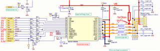
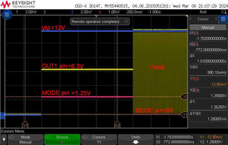
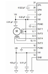
we are using the DRV8955 motor driver. We set its MODE to 330kOhm to GND (four independent High-Z, voltage on MODE_1.23V) and IN1-4 and EN1-4 pull to GND.

After that if we pull-up any one output by 1kOhm to VM=12V and on the output can be measured 6,3V. I think it should be 12V because the high-z state. On the oscilloscope all input and out pin are static state.

Do you have any idea?

  • Hi Pal,

    If possible, could you please send a picture of your layout and scope images to better understand this issue?

    Best,

    David

  • Hi David,
    thank you for your amswer, there is the picture here:

    You can see on the picture the used settings and the external 1kOhm pull-up resistor. The driver is in the 330k to GND mode (in theory, I hope).


    On the scope image:
    Blue channel: VM voltage
    yellow channel: DRV8955 OUT1 voltage
    pink channel: DRV8955 MODE pin voltage

    You can see: if the MODE pin voltage is 1.23V, the OUT1 voltage is about 6.3V, I think i should be 12V.
    If I changed the MODE pin voltage to 0V (Mode 0), the current control is active and the OUT1 output level changed between 0V and VM, it is normal.
    I do not understand, what is this current leakage in the 330k to GND mode. I repeated this test with the DRV8955PEVM board and the result was the same.

  • Hi Pal,

    I will review this issue in the lab and check with my team. I will reach out as soon as I know more. 

    Best,

    David

  • Hi Pal,

    The DRV8955, when configured for high-impedance mode (MODE = GND with 330kΩ resistor), offers individual control over each half-bridge output. While ideally you'd expect a perfect 12V at the output pin when connected to a 1kΩ pull-up resistor to 12V, a slight deviation occurs due to internal leakage current.

    I believe the attached load with the combined current draw through the resistor causes a voltage drop, reducing the voltage observed at the output pin compared to the ideal supply voltage. This effect becomes more pronounced with lower impedance loads.

    What is the impedance of your load? 

    If possible, could you measure the OUT1 voltage using the1kΩ pull-up resistor and no load attached?

    Best,

    David

  • Hi David,
    thank you for your answer.
    You asked me to measure OUT1 without load only with 1kOhm resistor. My measuring happened without load!
    We use this device to drive unipolar, bipolar and DC actuators, the load is depends on their type,
    the value is between 1 and 100 Ohm.
    Other effect: when I activated the SLEEP signal with this 1kOhm load, the OUT1 voltage is 10V.

  • Hi Pal,

    I will check with the design team on the leakage current spec. I will reach out on Monday with any information.

    When you say, "activated the SLEEP signal" does this mean you are putting nSLEEP = HIGH (waking up the device) or nSLEEP = LOW (putting device to sleep)? 

    Best,

    David

  • Hi David,
    the activation the SLEEP signal means that I put the device to sleep (0V). 

  • Hi Pal,

    Thank you for clarifying. 

    I am still waiting on the design team to get back. I will let you know tomorrow of any updates. 

    Best,

    David

  • Hi Pal,

    I'm am still waiting on test results from the design team. No updates yet, but I will reach out as soon as I know more. 

    Thank you for your patience.

    Best,

    David

  • Hi Pal,

    I just got word back from design. It looks like this voltage drop is caused by the leakage current.

    The response from design is below:

    "When the device is ON but OUT is Hi-Z the leakage is around 5.8mA nominally which means it will drop around 5.8V with a 1K resistor.

    For nsleep=0, the leakage is 1.8mA nominally.

    This leakage is present due to the strong pull downs in the high side gate taking current through diodes present between powerfet source and gate."

    Best,

    David

  • Hi David,
    thank you for your analysis.
    It means, when we drive an unipolar actuator (or DC), the recirculation current (fast decay) will have a little distorsion. After stopping the actuator this 5.8mA  always flows through the coils causing residual magnetism, so we always have to switch off VM.


    In the Low-current sleep mode the situation is the same. Do other pins have this kind of leakage?

  • Hey Pal,

    David is on PTO the next couple of days, I will help support. 

    In the Low-current sleep mode the situation is the same.

    I think it should be much less (about a third), down to 1.8mA in sleep mode, can you test/confirm this?  

    Do other pins have this kind of leakage?

    No, it should just be the output pins.  

    This leakage current will exist in any of our integrated devices, you would have to switch to a gate driver to fully eliminate it.  Look for the R_Hi-Z spec or similar in the datasheet if you look at other devices, though not all our datasheets list this spec. For example below from DRV8143 the leakage current will be between 12V/1.4kΩ=8.5mA to 0.185mA, though likely somewhere in the middle.  

    Best,

    Jacob

  • Hey Jacob,
    thank you for your support.
    You have right in sleep mode is this current is about 1.8mA.

    In the documentation of the DRV8955 I didn't find any specification about any Rhi-z impedance. Basically, we can live with this phenomenon, its effect can only be felt in the microstep control of unipolar actuators