This thread has been locked.

If you have a related question, please click the "Ask a related question" button in the top right corner. The newly created question will be automatically linked to this question.

DRV2605L: LRA drive - inconsistent behaviour in closed loop mode, too high current

Part Number: DRV2605L
Other Parts Discussed in Thread: DRV2605

Dear experts

In our project we are using the DRV2605L in combination with an LRA (240Hz resonance, 0.1...1.2Vrms drive voltage).
The DRV2605 is in closed loop mode with PWM input (f=20kHz, D=80%).

Issue 1
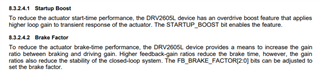
When we want to drive two haptic feedback pulses (just enable / disbale PWM), they look totally different. In the first pulse the DRV2605L outputs a much higher duty cycle for driving the LRA compared to the next pulse. This leads to a doubled current consumption and too high voltage for the LRA. We expect the DRV2605L to drive the LRA always the same (as in the second pulse). What causes the driver to behave like that? We do not feel a difference in the acceleration.

Below the two measured pulses with different zoom levels.
CH1 / CH2: OUT+ / OUT-
CH3: Signal from OUT+ filtered with RC LP-Filter (80Hz)

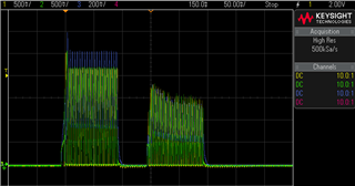
Zoom between first pulse / second pulse.

Startup first pulse

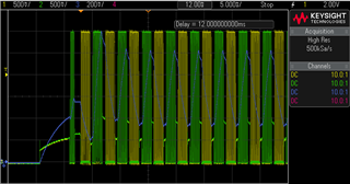
Startup second pulse

As a workaround we reconfigured the DRV2605L to work in open loop mode. There we had consistent results, but as there could be variations of the LRA manufacturer we are intended to use the closed loop mode.

Issue 2
We tried to use the autocalibration and diagnostic feature. However this did not work as expected:
- The diagnostic feature is always failing (DIAG_RESULT asserted). In an earlier state of the project we used an ERM and the actuator diagnostics worked well. Our LRA has a resistance of 19 Ohm. Is this possibly recognized as 'shorted'? I cannot find any information regarding this.
- We hoped to solve issue 1 using the autocalibration feature. This results were consistent, but did not solve issue 1. We noted that LRA_PERIOD was changing between 42 and 50 on the same system.

Thanks,
Roman

  • Hi Roman, 

    Thanks for reaching out. 

    1. The reason for the difference is our overdrive boost feature that is only available in closed loop mode, hence why you do not see it in open loop mode. I included a small description from the datasheet below. In overdrive, the voltage goes above the rated voltage but stays below the overdrive clamp voltage. To disable this feature in closed loop mode, you can disable the STARTUP_BOOST register. 

    2. If the device is in diagnostic mode and you trigger the process, the DIAG_RESULT will flag if it fails the diagnostic routine. If the device is in Auto Calibration mode and you fire the process, the DIAG_RESULT will flag if it fails the calibration routine. If you see DIAG_RESULT assert in diagnostics mode, please check the load connections. The minimum load impedance for DRV2605L is 8 ohms, so your LRA should be okay. If you see DIAG_RESULT assert in autocalibration mode, please refer to 8.5.6 Auto Calibration Procedure in the datasheet. 

    Also, the LRA_PERIOD should only be read while a waveform is being driven. 

    Hope this helps!

    Regards,
    Sydney Northcutt 

  • Hi Sydney

    1. we already disabled the overdrive boost feature. This does not solve our problem. When I trigger the DRV2605L, it sometimes controls the LRA with a high amplitude (higher than configured), sometimes with a low one, see images below. Nothing is reconfigured in between. Attached are all the bitfields of the DRV2605L.

    CH1: IN / TRIG, generated by function generator. D=80% / 0%.
    CH2: OUT+
    CH3: Signal after 200kOhm / 10nF RC LP-Filter connected to OUT-

                       |lra closed loop |
    field name         |calibrated      |
    a_cal_bemf         |154             |
    a_cal_comp         |10              |
    ac_couple          |0               |
    ath_filter         |1               |
    ath_max_drive      |255             |
    ath_max_input      |255             |
    ath_min_drive      |25              |
    ath_min_input      |25              |
    ath_peak_time      |1               |
    auto_cal_time      |3               |
    auto_ol_cnt        |2               |
    bemf_gain          |2               |
    bidir_input        |1               |
    blanking_time_1    |1               |
    blanking_time_2    |0               |
    brake_stabilizer   |1               |
    brt                |0               |
    data_format_rtp    |0               |
    dev_reset          |0               |
    device_id          |7               |
    diag_result        |0               |
    drive_time         |19              |
    erm_open_loop      |0               |
    fb_brake_factor    |3               |
    go                 |0               |
    hi_z               |0               |
    idiss_time_1       |1               |
    idiss_time_2       |0               |
    library_sel_0      |0               |
    library_sel_1      |0               |
    library_sel_2      |0               |
    loop_gain          |1               |
    lra_auto_open_loop |0               |
    lra_drive_mode     |0               |
    lra_open_loop      |0               |
    lra_period         |43              |
    mode               |3               |
    n_erm_lra          |1               |
    n_pwm_analog       |0               |
    ng_thresh          |2               |
    oc_detect          |0               |
    od_clamp           |137             |
    odt                |0               |
    ol_lra_period      |51              |
    otp_program        |0               |
    otp_status         |0               |
    over_temp          |0               |
    playback_interval  |0               |
    rated_voltage      |56              |
    rtp_input          |0               |
    sample_time        |3               |
    snt                |0               |
    spt                |0               |
    standby            |0               |
    startup_boost      |0               |
    supply_comp_dis    |0               |
    vbat               |141             |
    zc_det_time        |0               |


    2. I was able to solve the issue regarding the diagnose mode fail. The LP Filter connected to the LRA was too low impedance (20kOhm / 100nF). I inceased it to 200k / 10nF and it worked well. But issue 1 was not solved by this, even if I completely remove the filter.

    Regards,
    Roman

  • Hi Roman, 

    Correcting myself from my pervious statement, turning off the startup_boost does not fully turn off the over drive functionality. This is what is causing the amplitude difference you are seeing. To effectively turn off this feature in closed loop mode, you can set the overdrive and rated voltages to the same value. Please note that the rated voltage value is in Vrms and the over drive voltage is in Vdc, so some scaling will be needed. 

    As for the waveforms looking slightly different, closed loop mode is a feedback based feature, so there will be some variability. 

    In general, we do not recommend having an output filter on this device as it can negatively impact the feedback features.

    Regards,
    Sydney Northcutt 

  • Hi Sydney

    We solved the problem. One thing that caused loop instablity was a too high initial setting of the drive time (Adr 0x1B). Furthermore we decreased the overdrive voltage as you suggested.

    Thank you and best regards,
    Roman