This thread has been locked.

If you have a related question, please click the "Ask a related question" button in the top right corner. The newly created question will be automatically linked to this question.

DRV8718-Q1: VDS OCP

Part Number: DRV8718-Q1

Hi team,

My customer uses DRV8718SQRVJRQ1 to drive the solenoid valve in their project and meet blow issue now, could you please help review and give some comments? Thanks!

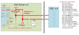
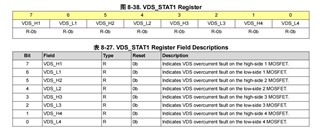
1. The low side drive is turned on continuously. When high side setting: PWM -0%, VDS_H1 is steady and does not disappear; PWM -100%, VDS_H1 is not triggered; PWM -100%, VDS_H1 switches back and forth between triggered and not triggered.

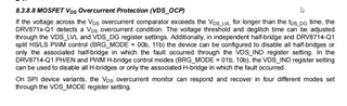
2. The VDS overcurrent detection mechanism is triggered when the high side is turned on and off. When the high side is turned off, the voltage of the VDS will naturally exceed the alert threshold, and an fault will occur (in theory, the overcurrent should not be triggered when the high side is turned off) 

3. Based on the above test phenomenon, the current chip scheme, seems to be unable to protect the load short circuit in PWM mode. Because the overcurrent fault can be inadvertently triggered when PWN is turned off.

Regards,

Ivy

  • Hi Ivy,

    Can they capture the output waveforms along with the current? Can they also provide if it is a HS or LS OCP and what half bridge? Can you also provide me with the VDS_LVL that is currently set for the relevant half bridges.

    Best,

    Keerthi

  • Hi Ivy,

    There is a circuit issue in the schematic. See below. SH2 must be connected to HB2 LS-FET DRAIN for VDS input for HB2 LS-FET. The two 100k resistors are not necessary - can be removed. 

    Constant current mode configuration looks fine. The HB2 LS-FET is switched ON. The HB1 HS-FET, set with diode free-wheeling and is controlled by PWM input on IN1 (not IN0). When PWM = 1, solenoid is energized and when PWM = 0 HB1 HS-FET will be OFF and recirculation current flows via passive freewheeling diode on HB1 side. The duty cycle will set the average drive current via the solenoid.

    What is "Current Drop Mode"? Why is HB2 made Hi-Z in this mode, HB2 LS-FET is OFF? HB1 HS-FET is still set with diode free-wheeling and is controlled by PWM input on IN1. What is the PWM input status on IN1 during this Current Drop Mode?

    I think the main issue was the missing SH2 connection. Please fix the circuit and try again. 

    Regards, Murugavel 

  • Hi!I am a hardware engineer from tuopu company, one customer of Miss lvy.The abnormal overcurrent situation has been solved. Unfortunately, we meet another problem on DRV8718. When we were preparing for some testing, just applying the same infrastracture showen below, the upper diode was destroyed, the other mosfets(HS & LS) and lower diode they were complete and functional. The upper diode's internal diode value 0.4V just gone, it's completely broken down. And the glue beneath the Rshunt was burnt yellow ,it seems like constant and great current flowing through the resistor(Rshunt)

  • Current Drop Mode is like that. In this design,we use the upper diode and mosfet as a  circuit for pulling all the energy to KL30_V. It's kind of diferent from the normal way that  using the lower mosfet and freewheel-diode to consuming the energy towards GND.By pulling energy to the power bus KL30_V, the current can be removed within 2ms shorter than GND circuit.

    Sorry,this photo isn't complete enough.In the schematic ,SH2 is linked well.

    In the BOM, the 100kR resistors isn't placed.

  • We think the load(like an inductor) is shorted,so that generates a great current  causing  the burnt yellow gule beneath the Rshunt and the disabled diode. But when we test it , only the Rshunt is burnt and disabled, the upper diode is of functional. The Rshunt we use is 1W 1206  20mR. And diodes are SB56AFC-AU (   If(av)=5A,Vrrm=60V,  Vf=0.39V@If=1A;Tj=25℃).Mosfet is BUK7K6R2 (Id=40A).

  • Hi,

    Nice to meet you!

    Good to know the abnormal overcurrent situation was resolved.

    "The Rshunt we use is 1W 1206  20mR.". This 1W resistor can handle up to 7A current. "And diodes are SB56AFC-AU (   If(av)=5A,Vrrm=60V,  Vf=0.39V@If=1A;Tj=25℃". It is possible the kickback voltage generated inductive load exceeded 60V and damaged the diode and when the diode was shorted high current flowed via the Rshunt. The MOSFET is also 40V rated might be better to use higher voltage rated. 

    "Current Drop Mode is like that. In this design,we use the upper diode and mosfet as a  circuit for pulling all the energy to KL30_V. It's kind of diferent from the normal way that  using the lower mosfet and freewheel-diode to consuming the energy towards GND.By pulling energy to the power bus KL30_V, the current can be removed within 2ms shorter than GND circuit.". This approach can likely generate higher voltage across the inductor. This could be measure with higher voltage probes. 

    Regards, Murugavel

  • Hi! Thanks for your advice,I have some futher questions.

    If the upper diode is damaged by hign voltage, it's supposed to be Vrms (42V) rather than Vrrm (60V).Moreover, no matter is the Vrms or Vrrm ,the other two mosfets only can stand with 40V (Vds@rated) , maybe it depends on the time or other factors.

    The power's voltage value I set maybe the main factor , do you think the higher power voltage I set ,the higher voltage the inductor will generate?

  • Hi,

    You said, "do you think the higher power voltage I set ,the higher voltage the inductor will generate?". Yes it is typically the case. Also the faster the current is broken through the inductor the higher the generated initial voltage will be from the inductor. 

    Regards Murugavel

  • Hi! I am so sorry to interrupt you again.Why would i consider this issue after getting off work for 3h?Haha. Had you get off work? 

    Today, I test this circuit.To my surprise, this circuit isn't controlled in the way I thought, it's just a normal high-side controlled half-bridge having nothing to do with the broken diode. It's my mistake. My software college they don't follow our advice ,fuck! They merely set the whole circuit as a half-bridge for the urgent EMC test.The whole working process is shown below. 

    So,wether the circuit is running or get stopped, the diode D1 isn't involved at all.

    As you considered, the burnt yellow gule beside Rshunt is caused by the shorten of D1.Maybe this can explain why the useless D1 get broken.In this way, it's more supposed that the D1 is shorted by external things, perhaps the  solder ball.The solder ball between the dual mosfets' drain makes the D1 get shorted, and then a great current less than 7A flowing through the whole circuit.

    Now i can only supect in this way,hahaha.

    Best regards Kong

  • Hi Kong,

    I'm based in the US, Dallas headquarters. I agree sometimes we keep thinking about the problems until we fully understand what is happening. 

    Thanks for the detailed drive schematic. The DRV8718-Q1 has internal smart gate drive which directly looks at the VGS charge voltage level and timing as well as performs handshake for proper drive. We recommend not to have any of the additional external components that you have, I have marked with "X". Our suggestion is to connect GH1 and GL2 to directly connect to the GATEs of the FETs. I also noticed C900, C903 and C904, 470nF fairly large value capacitor across the FETs. While powered up there will be a charge current spike depending on the supply impedance could over stress the diodes.

    In addition to all of the above for this bridge operation, consider the following sequence which would be our recommendation. 

    1) Energize the valve solenoid coil: First switch ON M2 with M1 OFF. Then apply PWM to M1 to activate the solenoid.

    2) If M1 has PWM control then during PWM OFF keep M2 ON always. This will allow the recirculation current to flow via D2 and the conducting M2. This would decay faster because the inductive energy is discharged down to the forward voltage of D2 ~ 0.3V. If you switch OFF M2 then discharge level will be only until KL30_V - 2*VF or KL30_V - 0.6V. 

    3) Same applies when you power off the valve solenoid. First switch OFF M1. Wait for a few milliseconds to allow all the energy in the coil to be dissipated via M2 and D2. If you want to turn OFF M2 you can do it after this time.  Also it is okay to leave M2 ON always.

    I hope this helps. Thanks.

    Regards, Murugavel