This thread has been locked.

If you have a related question, please click the "Ask a related question" button in the top right corner. The newly created question will be automatically linked to this question.

DRV8262: Questions about DRV8262

Part Number: DRV8262
Other Parts Discussed in Thread: DRV8412

Dear TI experts,

My customer considers DRV8262 for their new project. and They have some questions as below. Could you check these questions?

1. Can My customer use DDV package of DRV8262? (I can see only DDW package in product page.)

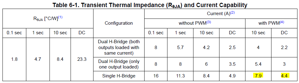
2. What is the meaning of DC on the table below? Is it not a pulse, contimuous load?

3. Is OCPM pin just determine the type of recovery? (latch-off type recovery=low or automatic recovery=high) Anyway My customer should determine this pin set high or low. right?

4. About overcurrent protectoin, Can I adjust the value of overcurrent detection? (DRV8412 has OC_ADJ pin and I can program the value using resistor.)

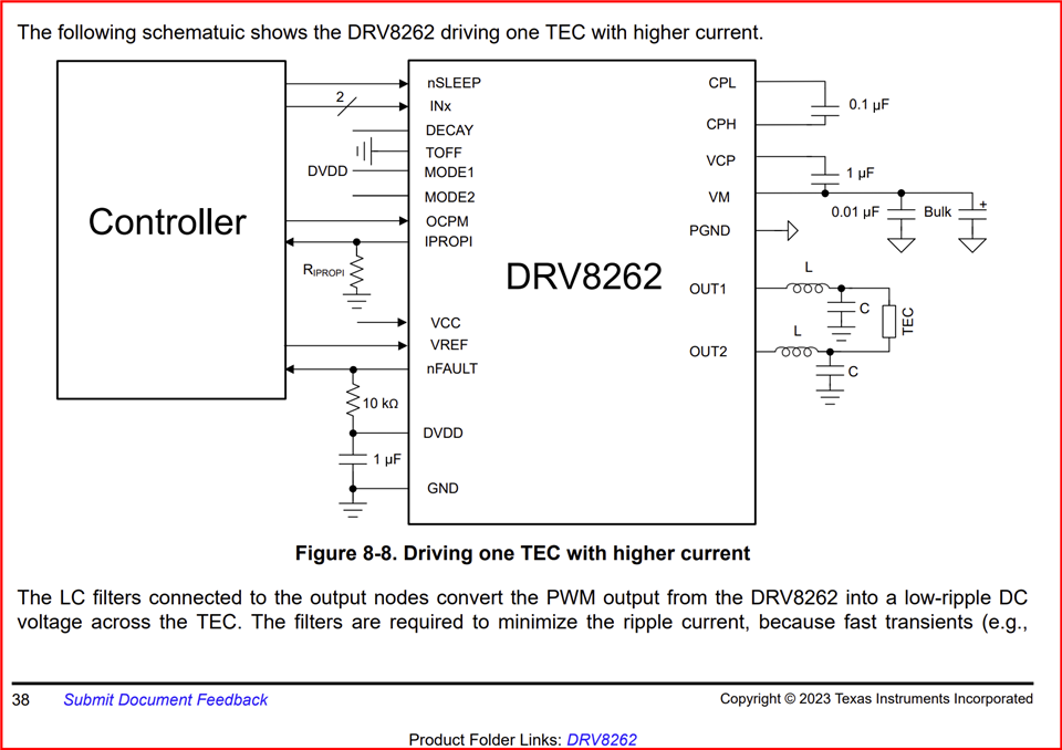
5. THey will connect peltier to the output of DRV8262 in single mode.

Can I use all out 1 pin tie together (P4,P5,P6,P17,P18,P19) and use only 1 inductor? or use 2 inductors? (P4,P5,P6 and P17,P18,P19 separately)

6. When I use IPROPI pin in sigle mode, Can I recognize foward current or reverse current?

7. My customer will use 200KHz frequency for PWM mode. Is there any concern for schematic?

Best regards,

Chase

  • Hi Chase,

    1. Yes. DDV package is expected to be available by e/o this month.

    2. DC is the continuous current.

    3. Yes this is correct.

    4. It is a fixed value in the DRV8262.

    5. "Can I use all out 1 pin tie together (P4,P5,P6,P17,P18,P19) and use only 1 inductor?". Yes, please refer to the below figure from the datasheet.

    6. Yes. Be sure to have IPROPI1 and IPROPI2 tied together as mentioned in the datasheet for parallel H-bridges.

    7. Our recommended layout is for the operating range of the device. The EVM Altium files can be downloaded from the EVM webpage, https://www.ti.com/lit/zip/slor128

    Regards, Murugavel 

  • Dear Murugavel,

    Thank you for your support.

    I have more question about question no.5.

    You said that

    "Can I use all out 1 pin tie together (P4,P5,P6,P17,P18,P19) and use only 1 inductor?". Yes, please refer to the below figure from the datasheet.

    but the figure you attached shows that there are 2 inductors (each OUT1 and OUT2) Should I just follow the figure and use 2 inductors?

    Best regards,

    Chase

  • Hi Chase,

    I meant one inductor each for all the OUT1 and all the OUT2 pins combined. LC filter is used for filtering the ripple for the TEC itself. If you desire to use one LC in the path of the driver to TEC theoretically that should be fine but to achieve the same amount of ripple as 2x LC the sign LC should have double the inductance and capacitance. The values are defined by the PWM frequency and the output ripple desired by the customer. 

    Regards, Murugavel