Hi,
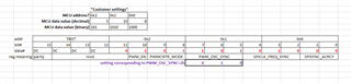
The customer uses f28388 to control the DRV8311p. The f28388 outputs a 20khz synchronization signal to the pwm_sync pin of the drv8311. The PWMG_CTRL register is configured as pwmg_ctrl_data=(0x1《10)|(0x0 《8)|(0x2 《5).
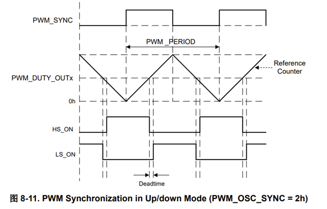
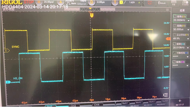
After configuring the pwm duty cycle, the pwm output pin OUT A/B/C output waveform does not correspond to the manual waveform, why the output waveform is different from the manual?
-
Data sheet waveform:
-
The actual test waveform:
Please help support. Thanks~