This thread has been locked.

If you have a related question, please click the "Ask a related question" button in the top right corner. The newly created question will be automatically linked to this question.

DRV8462EVM: it seems the SPI transmission doesn't work

Part Number: DRV8462EVM
Other Parts Discussed in Thread: DRV8462,

Hi,

the DRV8462EVM works with the GUI, but when I try to control the DRV8462 with an external MCU it doesn't work.

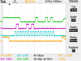
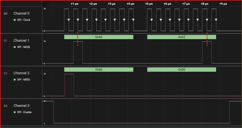
When I send 0x4500 on the SDI to the DRV8462, 0xE045 comes back on the SDO. But 0xExxx means that the UVLO bit is set.

But I have 24VDC on the VM terminal and the 3.3V comes from the external board. Booth LED for Vin an 3V3 are on and there are 5V on the DVDD pin.

What could be wrong?

  • Hey Albert,

    Have you used a scope or a logic analyzer to compare a SPI packet from the EVM vs your SPI packet from external MCU? Make sure you're using SPI Mode 1.

    For clearing the UVLO error, send a nSLEEP reset pulse of 30us duration to clear the latched fault. 

    Best,

    Jacob

  • Hi Jacob,

    here is a print from the scope.

    The SCS signal is in yellow, the clock is in blue, the SDI is in red and the SDO is in green.

    As you can see, I had sent the code 0x4500 and got back the code 0xE045 (UVLO is high).

    Adress 05 means the CTRL2 register and the default state of this register should be 0x06.

    Of course I set mode to "1" and 30us before the SCS was low the nSleep was also 30us low.

    The same question as above: What could be wrong?

    Best,

    Albert

  • Hi Albert,

    In your capture the clock phase CLKPH is not matching with the DRV8462 SPI CLKPH requirements. This should be an SPI mode setup in your MCU. Some MCU vendors don't really match mode numbers exactly. You may be reading out an incorrect SDO value because of this incorrect CLKPH setup.

    Also whenever you wakeup the device nSLEEP 0 to 1, you must wait tWAKE (0.25ms) datasheet specification, before starting an SPI transaction. 

    See datasheet page-71.

    Here's an example capture of an actual functioning SPI transaction capture:

    The gap between the two bytes is normal for some MCUs but don't impact operation. Two bytes with no gap is fine as well, CLPH alignment is important.

    Regards, Murugavel