Other Parts Discussed in Thread: ADS7830
Hello,
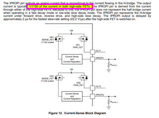
We are currently in the development stage, designing a control system using drv8873H chips to drive 24v brushed motors. These motors can have current spikes up to 5.5A during normal operation but generally run at around 0.5A. Our question relates to the use of the IPROPI current sense pins. Due to the motors operating conditions, we have sized the rSENSE resistor at 1k, which gives us current mirroring to 5.5A. We feed this output to an ADS7830 ADC chip which converts it to digital for use by our micro for current sensing. Generally speaking, we have followed the Texas Instruments design examples found online when designing the current sense circuit. We tied both IPROPI1 and IPROPI2 together as per figure 14 of the datasheet, as we don’t require the currents flowing through the individual half-bridges to be separated. We are operating the drive chips in PH/EN mode, PWM’ing IN1 and toggling IN2 as required for forward and reverse operation.
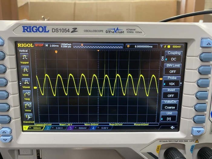
Currently, the current mirror output displays a sinusoidal frequency that appears to correspond to the same frequency of oscillations in the motor current.
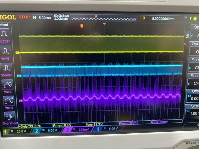
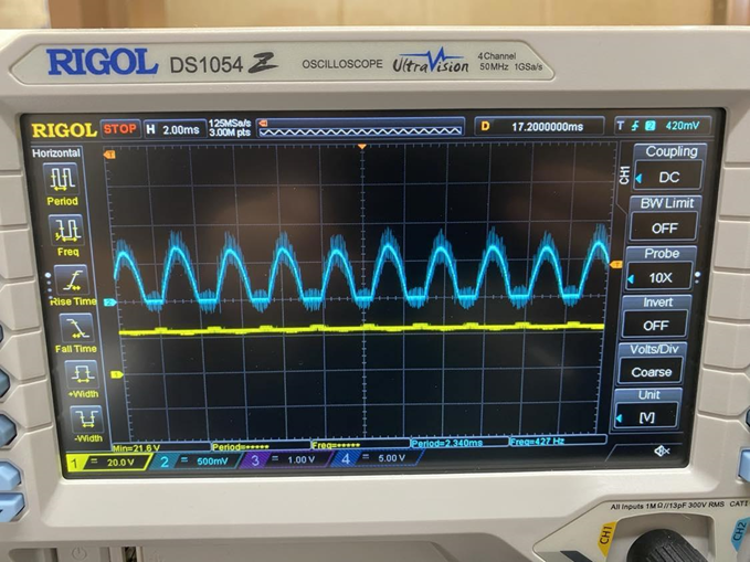
As you can see, the waveform (current signal in blue) appears to be clipped at 0V, with the above reflecting the below capture of the motor current captured using a 1 ohm shunt resistor:
We note the above behaviour on both our prototype board as well as the DRV8873H-EVM board.
We are hoping to use the current sense output to monitor the avg current draw of the motors to aid in determining health of the pumps in the field. Is the above-described current sense waveform as expected? We were assuming, based on the example circuit diagrams and schematics, that the current sensing circuit within the drive chip would output a more filtered and usable analog waveform. If this is the expected waveform (with IPROPI1 and 2 connected like such), are you able to advise on a fix to create a more smooth filtered result? Can we introduce a RC low-pass filter to reduce the amplitude of the oscillations and/or use a high sampling rate and use software to average the results to smooth the impact of the analog signal? Please note that we do not require a high level of accuracy or acute time-sensitive current sensing, so a filter delay is unlikely to be problematic.
Thanks.