Dear Expert
Problem decription:
1.Is the waveform of the phase current and line voltage output of the FOC motor control attached below standard and can it be optimized?
2. Is it necessary to go through RC filtering to see the standard phase current saddle shoe waveform and line voltage sine wave after testing the FOC control output?
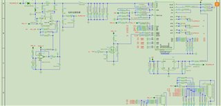
At present, the circuit design based on DRV8316R chip is based on the demo development board of DRV8316xEVM, and the control algorithm adopts FOC control. The specific circuit schematic design is as follows:
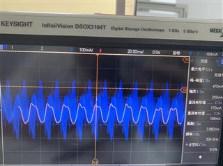
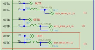
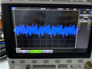
Based on the TP64 test point, test the phase current and line voltage in the C direction:
The test phase current is shown in the following figure, but the expected horseshoe saddle waveform was not obtained:
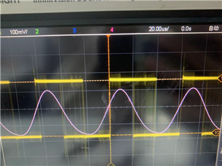
However, after digital filtering, it was found that the phase current can display a saddle shoe waveform, and the line voltage can display a sine wave. (The pink line is the waveform after digital filtering, the blue waveform is the original phase current, and the yellow waveform is the line voltage with constantly changing frequency)