Hello TI Support and Community,
I am currently working with the DRV8701 motor driver and came across what appears to be contradictory information in the datasheet regarding the IDRIVE pin configuration for disabling the Overcurrent Protection (OCP) monitor.
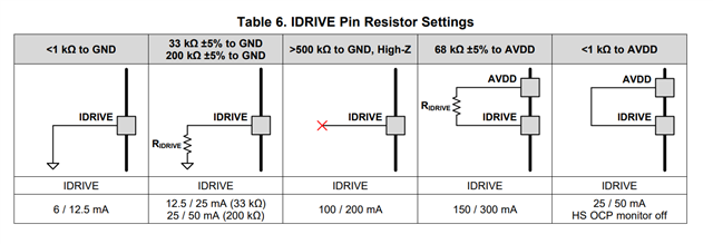
As per Section 7.3.6 of the datasheet, it states that shorting IDRIVE to AVDD will disable the VDS OCP monitor on the high-side FETs. The implication here is that a direct short is required for the OCP to be disabled, resulting in an IDRIVE configuration as a 25-mA source and 50-mA sink.

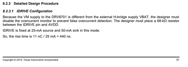
However, Section 8.2.3.1 of the same datasheet specifies that the designer must place a 68-kΩ resistor between the IDRIVE pin and AVDD to prevent false overcurrent detection due to the VM supply to the DRV8701 being different from the external H-bridge supply VBAT. This configuration also mentions an IDRIVE fixed at 25-mA source and 50-mA sink.

Here lies the confusion: one section suggests a direct short, while the other specifies using a resistor. Could you please clarify the correct method of disabling the OCP monitor for the DRV8701?
Thank you in advance for your assistance!

