This thread has been locked.

If you have a related question, please click the "Ask a related question" button in the top right corner. The newly created question will be automatically linked to this question.

DRV103: drv103u is not giving right duty cycle.

Part Number: DRV103

Hello,

I am Using drv103u to control the  proportional valve using microcontroller, valve ratings: 24V , 7watts, 290mA , 82 ohm resistance. I tried the circuit like figure 18 in the datasheet, but I get 100% duty cycle if I ask for 50% or any other duty cycle. I GET CONSTANT 24v and 290mA OUTPUT. what might be the possible fault. instead of TTL input I am giving input from PSU. you help in this matter is greatly appreciated. 

  • Hey Showrya,

    instead of TTL input I am giving input from PSU

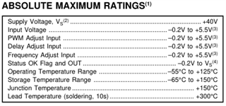
    Can you elaborate on this?  Make sure the input voltages comply with the absolute maximum ratings table 

    What is your voltage on the Delay Adjust pin?  If below 2.6V device will be 100% ON.  Also what is your voltage or resistor for the Duty Cycle Adjust pin?

    Best,

    Jacob

  • Hello Jacob, 

    Thanks for fast response,

    circuit configuration:

    pin connections:

    pin1 : voltage from the DAC

    pin2: floating

    pin3; 100k(50KHz)

    pin 4: GND

    pin 5: anode of 1n5822 and terminal of valve.

    pin 6: supply voltage with 22uF bypass. also cathode of fly back diode and other terminal of valve .

    pin 7: floating

    pin 8: input from PSU via voltage divider(2V).

    today chip started working as I used the new chip. But there are some issues/doubts I have.

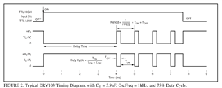
    1. after I turn off the input signal, still it shows the PWM output(oscillator probe is connected to pin 5 and GND). (according to data sheet it should off below 1.7V

    2. can I control the frequency through voltage instead of resistor?

    3. right now I am giving the supply voltage as 27V which is connected  to both  Vs and valve, but what voltage should I consider for the valve of 24V?

    4. I am doing voltage controlled duty cycle provided from the DAC, would it take input from the microcontroller(digital input) or I should convert it using DAC before giving it to the duty cycle adjustment pin?

    "Can you elaborate on this? " 

    In datasheet it says we have to provide TTL input to input pin, but I am giving dc input from Power supply unit to voltage divider and giving it to pin 8.

    "What is your voltage on the Delay Adjust pin?"

    it varies from the range 4.9 to 5.3V  varies based on the  the duty cycle voltage.

    "Also what is your voltage or resistor for the Duty Cycle Adjust pin?"

    giving voltage from DAC from 1.3 to 3.5 volts

  • Hey Showrya,

    today chip started working as I used the new chip

    That's good!

    it varies from the range 4.9 to 5.3V  varies based on the  the duty cycle voltage

    Make sure this voltage does not exceed 5.5V as that could damage the device.

    2. can I control the frequency through voltage instead of resistor?

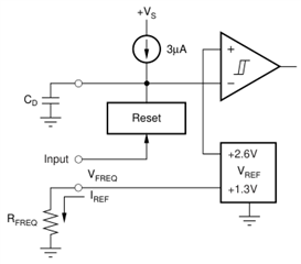
    Ahh sorry looks like I was mistaken, it has to be a resistor I believe looking at its block diagram.  

    3. right now I am giving the supply voltage as 27V which is connected  to both  Vs and valve, but what voltage should I consider for the valve of 24V?

    No change, Vs on the device can be 8V to 32V no problem. 

    4. I am doing voltage controlled duty cycle provided from the DAC, would it take input from the microcontroller(digital input) or I should convert it using DAC before giving it to the duty cycle adjustment pin?

    The pin wants a voltage, so if you did use a PWM from the microcontroller I would add a low-pass filter to convert the digital PWM signal into an analog voltage.  

    For testing you might want to try just using a resistor for it, so you can isolate whether the DAC is causing issues.

    Best,

    Jacob

  • 1.after I turn off the input signal, still it shows the PWM output(oscillator probe is connected to pin 5 and GND). (according to data sheet it should off below 1.7V)

    could you please explain what might be the reason.?

  • Not sure, I don't think that is expected behavior.  Could be damaged device?  Does it stay on continuously, or just for a few ms? 

    Looks like voltage will stay high, but current will be zero. 

    Note that the output will be disabled below 1.2V and enabled above 2.2V.  Between 1.2V and 2.2V is a gray area, don't know what the behavior will be.  

    Best,

    Jacob

  • hello,

    I don't think the device is damaged, because when I vary the duty cycle Via DAC, it actually gives the right duty cycle at output. when I am doing this, if I disconnect the input, still it will give the output. also I want to know what exactly is TTL input is and what is the difference between analog input and TTL input. and how can I generate it?

    regards,

    Showrya

  • Hey Showrya,

    what exactly is TTL input is and what is the difference between analog input and TTL input

    TTL input just means it supports TTL voltage levels, which are where low is <1.2V and high is >2.2V in this case.  for TTL stands for transistor-transistor logic. This is an old-fashioned way to describe an input, just saying that it can handle up to 5V not just typical 3.3V directly from a microcontroller.    

    disconnect the input

    Ahh, well disconnecting the input is different from driving the input low.  Since the device doesn't appear to have a pull up or pull down resistor on the input pin, when the input goes Hi-Z (disconnected) then it will likely maintain the previous voltage state.  It might eventually float up/down to the other state.  Since it's Hi-Z it's unknown what voltage the device will read. 

    Best,

    Jacob

  • Hello, 

    I have on more question, Lets say I used 24V valve, I will provide 26V as supply voltage to drv103, which is also connected to valve. Now if I replace the 24V valve by 12V valve and if I keep supply voltage same, it wont give right output, what might be the reason and also what might be the possible solution?. Once I give the supply voltage, I don't want to change it irrespective of the valve I am using.

  • Hey Showrya,

    Correct, the device just switches the voltage you give.  So you would have to change supply voltage to 12V for 12V valve.  Or you could PWM the output and add a R/C filter to create a rough analog voltage from the PWM signal

    Best,

    Jacob