This thread has been locked.

If you have a related question, please click the "Ask a related question" button in the top right corner. The newly created question will be automatically linked to this question.

DRV8434AEVM: drv8432dkdevm user manual

Part Number: DRV8434AEVM

Hi,

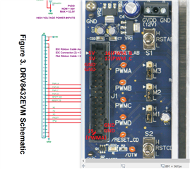
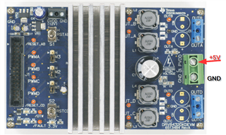
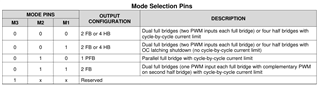
I want to drive a brushless motor using the drv8432dkdevm, but couldn't find out, which pins I have to use for the PWM-signals.

Therefore I searched for the manual of the drv8432dkdevm, but I didn't find it anywhere.

Where can I download it ?

(I need to add a part number here in the forum, but it does only accept the DRV8434AEVM. But I want to use the DRV8432AEVM)

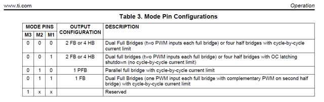
And do I need to send the PWM-signal AND the inverted signal to drive the motor ? Or only the pwm-signal ?

thanks,

  • Hey Maik,

    Does this look right?  

    EVM User's Guide: DRV8432EVM Motor Drive Evaluation Board

    DRV8432EVM User Guide.pdf

    If you're driving a brushless (BLDC) motor I highly recommend checking out our BLDC product line instead.  The DRV8432 device is also EoL so you will not be able to order the part in the future.  

    Best,

    Jacob

  • Thanks. The manual looks right.

    I have written a program in c on an esp32 that creates PWM-Sinus-signals and want to drive a BLDC-Motor with the board.

    There is a PWM-signal for U, V W and 3 inverted signals. Is it right that I don't really need the inverted signal ?

    The manual only says PWM_A, PWM_B and PWM_C.

    In the manual there is a circuit diagram that shows the pins of the connector. PWM is from PIN 15 to PIN 17.

    Is the pin on the upper left Pin 1 and the Pin on the lower right Pin 15 or how is the connection numbered ?

    Am I right that I need to put 5V on pin 1 and 5v on pin 30 ?

    Is there a reason why you can't recommend the board for the motor ? I want to use it for my theses. The first goal is to only get the motor running.

    thanks...

  • Hey Maik,

    A few resources we have on BLDC control:  

    I think those will teach you more than I know about BLDC drivers.  

    It took some digging but I was able to find the board files for this EVM:  https://www.ti.com/tool/download/SLOC273/ sloc273.zip

    Unzip that and open the Schematic PDF for circuit diagram.

    Is there a reason why you can't recommend the board for the motor ?

    It is a very old and discontinued device, and we have many better BLDC drivers.  Are you planning to implement FOC or something fancy?  The fastest path to spinning a BLDC motor would be to use a sensorless BLDC part, such as https://www.ti.com/tool/MCT8329EVM for example.  

    Also FYI, our EVMs are designed to work with the Web GUI for product testing.  I would look up Arduino-compatible BLDC motor drivers if you wanted the easiest route for hobby-level microcontroller use with a BLDC motor.  I've used the SimpleFOC boards myself in the past.  TI motor driver EVMs will also work, but they are large and expensive compared to hobby BLDC drivers. 

    Best,

    Jacob

  • Thanks a lot for your help, Jacob,

    the first goal is to program the microcontroller to spin the motor.

    Maybe in the future it has to do more complicated things, but at the moment its ok to only spin the motor and regulate the speed of the motor.

    Did I interpret the pins correctly ?

    Where should I the 5V-Powersupply (+5 and ground) and where should I connect the PWM-Signals and the ground from the microcontroller ?

    And why are there multiple ground and +5V-Inputs ?

    Thanks...

  • Hey Maik,

    Where should I the 5V-Powersupply (+5 and ground) and where should I connect the PWM-Signals and the ground from the microcontroller ?

    5V and GND on the green screw termpinal.  5V onto PVDD, GND on to GND.  

    PWM signals can go onto the orange test points PWMA, PWMB etc, or on the ribbon cable header as you show.  To confirm you got the pins right I would use a multimeter to test for continuity between a test point and the header pin, like measure between PWMC and pin 17 on the header. 

    I don't think your diagram is correct for the pins.  See the PCB layout in the user guide - you can trace the signals from the orange test point to the header. See the below image where I used red pen to trace PWM A/B/C to their pins 

    And why are there multiple ground and +5V-Inputs ?

    For current capability.  The cable on those ribbon cables is typically very small, often 26-30AWG.  A 28AWG wire current rating is around 1.4A.  If you parallel them you can roughly add up the current rating, so 2.8A for two wires etc.  The 5V rail shouldn't need more than 1.4A but better safe than sorry.  

    Best,

    Jacob

  • Thanks a lot. That really helps me.

    So I will connect

    - 12V to GVDD and GND

    - Motorpower 0-52V to PVDD

    - The PWM-output 1 of the microcontroller to PWMA-Testpoint

    The PWM-output 2 of the microcontroller to PWMB-Testpoint

    - The PWM-output 3 of the microcontroller to PWMC-Testpoint

    - Does the GND-PIN of the Microcontroller go to any gnd-pin on the board ? 

    The microcontroller only has an output of 40mA at the pins.

    Do I need a positive AND an inverted PWM-Signal for every phase ?

    The motor has 3 Phases U, V, W


    Thanks

  • Hey Maik,

    - 12V to GVDD and GND

    - Motorpower 0-52V to PVDD

    - The PWM-output 1 of the microcontroller to PWMA-Testpoint

    The PWM-output 2 of the microcontroller to PWMB-Testpoint

    - The PWM-output 3 of the microcontroller to PWMC-Testpoint

    Looks good. 

    - Does the GND-PIN of the Microcontroller go to any gnd-pin on the board ? 

    Yes

    The microcontroller only has an output of 40mA at the pins.

    That will be more than enough, our pins typically take <1mA

    Do I need a positive AND an inverted PWM-Signal for every phase ?

    The motor has 3 Phases U, V, W

    That I am not sure about, that's getting into BLDC commutation.  Unfortunately I only really know Brushed DC motor and Stepper Motor driving.  You can see some of those app notes I linked previously.  I know you'll also need position feedback of your BLDC motor, typically with 2 Hall sensors located on the PCB of the BLDC motor to detect the shaft position.  Then you can apply your trapezoidal or sinusoidal control scheme.  

    Best,

    Jacob 

  • Thanks. I managed to get Output A and B running.

    Output C doesn't show any curve, although PWM_C-Pin is connected.

    This is what the Output looks like on the oszilloscope:

    Output C is zero. Maybe you have an idea why this happens ?

    Maybe I have to configure the board differently ?

    The microcontroller Pins go directly to the PWM_A, PWM_B and PWM_C-pin on the board and I haven't used inverted PWM-Pins.

    Thanks... 

  • Hey Maik,

    Please see the DRV84x2 datasheet: https://www.ti.com/lit/ds/symlink/drv8412.pdf 

    I believe you'll need to be in the 4 Half-Bridge mode, one of the first two modes here:

    Best,

    Jacob