This thread has been locked.

If you have a related question, please click the "Ask a related question" button in the top right corner. The newly created question will be automatically linked to this question.

DRV8308: CP fail

Part Number: DRV8308

Hi, all

We are working on the project using drv8308.
I'm testing the board I designed.

The motor works well, but reading the motor register confirms the CP fault.
1uf-25V capacitor between VCP (28) and VM (27)
Does changing the capacitor to 1uf-50V fix the problem?

I'd like to try changing that capacitor, but I don't have 1uf-50V.

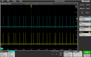
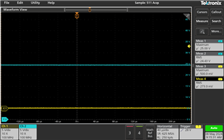
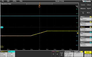
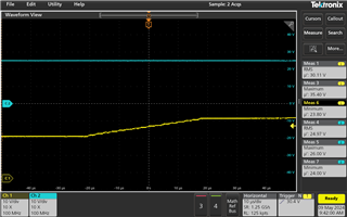
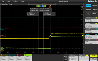
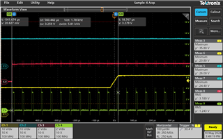
When the VCP voltage is measured, 34.4V is measured.

Is there a way to fix the CP failure?

  • Hi Shshin,

    What is the capacitance and voltage of the capacitor between CP1 and CP2?

    1uf-25V capacitor between VCP (28) and VM (27)
    Does changing the capacitor to 1uf-50V fix the problem?

    We recommend using a VCP-VM capacitor that has a voltage rating greater than or equal to 35V. Using a capacitor rated for less than 35V could lead to the capacitance becoming to low due to ceramic capacitor derating. 

    If you have not already, can the CPFAIL bit be manually cleared after the device is powered on? Also, can it be checked if the CPFAIL bit asserts again if the CPFAIL bit is cleared when the motor is running?

    Regards,

    Joshua

  • Hi Joshua. 

    I wrote down the answer to your question below.

    Q1: What is the capacitance and voltage of the capacitor between CP1 and CP2?

    => The capacitor connected to cp1 and cp2 is 0.1uf-50V

         It is a waveform of Cp1 and Cp2 when the motor is in operation.

         CP1 : Yellow , CP2 : Blue

    It is the waveform of Cp1 and Cp2 when the motor is not operating.

     CP1 : Yellow , CP2 : Blue

    Q2 : If you have not already, can the CPFAIL bit be manually cleared after the device is powered on? Also, can it be checked if the CPFAIL bit asserts again if the CPFAIL bit is cleared when the motor is running?

    => When power is applied to the board, the CPFAIL bit is 0. When the motor operates, the CPFAIL bit is 1.
    If I manually change the CPFAIL bit to 0 when the motor is running, the cpfail bit remains 0.

    I don't have a 1uf-50V capacitor. It takes some time to buy. However, before I buy, I want to make sure this is resolved.

    Ragards,

    Shin

  • Hi Joshua.

    Today I changed to 1uf-50V and tested it. The CPFAIL bit is set to 1 when the motor is running.

    When the motor is running, after setting the CPFAIL bit to 0, the cpfiale bit remains 0. However, when the motor is stopped and operated again, the CPFAIL bit becomes 1 again. 

  • Hi Shshin,

    Can you provide a capture of the VM voltage and the VCP voltage when starting the motor? I want to check if the voltage on VM is dipping when the voltage on VCP dips.

    Regards,

    Joshua

  • Hi Joshua. 

    Here is a waveform measuring VCP and VM. 

    In my opinion, the VM voltage does not drop when the VCP voltage rises.

    Blue : VM / Yellow : VCP 

    Thank you for your help.

    Ragards,

    Shin

  • Hi Shin,

    From the capture it appears like the device is coming output of a standby or sleep mode or powering on. If the ENABLE bit is set to inactive the VCP and VREG will be disabled. When VREG and VCP are disabled, VCP will be ~VM voltage and VREG will be ~0V. Can you check if the ENABLE and/or RESET pins are changing states close to when the VCP begins to rise? If these pins are changing states when the device is coming out of or going into a sleep mode this will disabling/re-enable VCP causing CPFAIL to re-assert.

    If the ENABLE and RESET pins are not changing states can you provide a capture of VCP, VREG, ENABLE, and the phase current at U starting when the device is powering up and including spinning the motor, stopping the motor, and then spinning the motor again?

    Regards,

    Joshua

  • Hi Joshua,

    Blue : VM , Red : ENABLE, Yellow : VCP, Green : FAULTn 

    FAULTn signal changes to High->low->high when the motor is running, is this normal?

    The meaning of this question is, does the FAULTn signal keep Hgih when everything is normal?

    Why does the FAULTn signal change to high again?

    Blue : VM, Red : ENABLE, Yellow : VCP, Green : CLKIN

    Can Cpfail happen because the SCLK signal goes straight in when the ENABLE signal changes to low->high?

    Does the VCP voltage rise if there is no PWM input in the CLKIN and the ENABLE signal is entered as low->high?

  • Hi Shin,

    Please allow me some time to look into your questions. I will get back with you on Monday.

    Regards,

    Joshua

  • Hi Shin,

    FAULTn signal changes to High->low->high when the motor is running, is this normal?

    If this is occurring when the motor is spinning and without ENABLE being provided a signal that is low->high or high->low then there is an issue, please provide the fault being reported. If this question is related to the capture please see my comment to the next question below.

    Why does the FAULTn signal change to high again?

    I see that the enable bit is low and then goes high near the beginning of the captures. When ENABLE is low the device is put in a low power state were all analog circuitry is disabled including the charge pump (VCP) (see section 7.3.3 of the datasheet). When ENABLE is set back to high the DRV8308 goes though a wakeup routine which can take a maximum of 1ms (see section 6.6 of the datasheet).During this wakeup time the analog circuity is turned back on, although FAULTn is woken up before VCP in the wakeup sequence which leads to the FAULTn pin being pulled low since VCP is below the CPFAIL threshold. When the VCP pin wakes up the FAULTn pin will be pulled high since the VCP voltage is now above the CPFAIL threshold.

    Does the VCP voltage rise if there is no PWM input in the CLKIN and the ENABLE signal is entered as low->high?

    Yes the VCP voltage will rise even if there is no PWM input into CLKIN when ENABLE is set from LOW to HIGH.

    Can Cpfail happen because the SCLK signal goes straight in when the ENABLE signal changes to low->high?

    We expect a CPFAIL to occur anytime the ENABLE is provided a low->high signal. When ENABLE is provided a low signal VCP should go from >VM+3V to ~VM.

    Regards,

    Joshua

  • HI Joshua.

    Red : FAULTn, Yellow : ENABLE, Blue : VCP 

    Looking at this waveform, when the ENABLE changes to Low-> High, the FALTn signal appears to be output as High-> Low

    because the VCP is before the VM +3V voltage.

    After the VCP voltage rises, the FAULTn signal changes to Low->High. 

    Is it correct that the CPFail bit does not automatically change to 1 -> 0 at this time? 

    Should the user directly set the Cpfail bit to 0?

    Is there any way to quickly increase the VCP voltage? 

    I think CPFAil will definitely occur on the board I'm testing 

    Is there a way to prevent CPFAIL from happening?

    Is it helpful to measure the signal on the HSU side when the ENABLE signal changes to low->high?

    Wednesday is my day off.

    I will test it on thursday.

    Please reply.
    Thank you for your help every time.

    Regards,

    Shin

  • Hi Shin,

    Is it correct that the CPFail bit does not automatically change to 1 -> 0 at this time? 

    Should the user directly set the Cpfail bit to 0?

    Correct, the CPFAIL bit will not automatically change from a 1->0. CPFAIL will remain set as 1b until a 0b is written to the CPFAIL bit by the user. After setting ENABLE from LOW->HIGH and waiting 1ms, you can set the CPFAIL bit to 0b to clear the fault. If the CPFAIL bit gets set again without the ENABLE bit going from LOW->HIGH then a issue maybe occurring.

    Is there any way to quickly increase the VCP voltage? 

    The time that the VCP voltage rises after the ENABLE pin is pulled high cannot be changed. This time will vary from device to device due to production variation but we expect that VCP will rise before the 1ms wakeup time.

    Is there a way to prevent CPFAIL from happening?

    When ENABLE goes from LOW->HIGH CPFAIL cannot be prevented. CPFAIL occurring when ENABLE goes from LOW->HIGH is expected.

    Regards,

    Joshua

  • Hi Joshua

    After the ENABLE signal is changed to low->high,
    Write the CPFAIL bit to 0 after 1 ms.

    Is this normal?
    Isn't it a problem to use the product?

     If you tell me it's normal, I'll finish this problem.

    Regards,

    Shin

  • Hi Shin,

    It is normal to have to write 0b to CPFAIL one time after ENABLE is changed low->high. Doing this should not cause a problem when using the DRV8308.

    Regards,

    Joshua

  • Hi Joshua

    Thank you for your response in the meantime.

    Regards,

    Shin