This thread has been locked.

If you have a related question, please click the "Ask a related question" button in the top right corner. The newly created question will be automatically linked to this question.

DRV8245-Q1: DRV8245-Q1MCU control pin

Part Number: DRV8245-Q1


Hello.

I would like to ask about DRV8245-Q1 device.


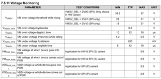
1. In SPI(P), (VM undervoltage translators) is a question about how long and how much voltage it is.

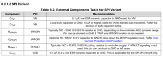
2. Apart from the SPI connection, which pins should be essential to the MCU? Is there any function that SPI can replace?

  - EN/IN1, PH/IN2, nSLEEP, nFAULT

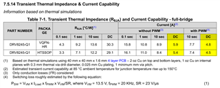
3. I would like to ask if I can use more than 5.5A continuously (1oz 6Layer)

  • Hi, BSM team

    One of my Key customer, KyungShin is trying to design DRV8245-Q1 in next gen project.

    Here is additional comment on each question.

    1. customer wants to know VM undervoltage transient condition. what is threshold and deglitch time? below table might be answer. can you confirm?

    2. There are several HW control PIN such as EN/IN1, PH/IN2, nSLEEP, nFAULT. Can you point out unnecessary pin which is duplicated with SPI control?

    That is, when designing schematic, are there any PIN not to need to route if SPI interface can support the feature?

    3. Customer needs 5.5A continuous current. All of us understood it totally depends on PCB design. nevertheless, do you have any comment how to design PCB to support 5.5A continuous current?

  • Hey Chae and Luke,

    1. Yes, that is the correct specs for undervoltage.  

    2. There are several HW control PIN such as EN/IN1, PH/IN2, nSLEEP, nFAULT. Can you point out unnecessary pin which is duplicated with SPI control?
    • nFAULT: Optional, FAULT_SUMMARY and STATUS registers give more info than it.  Often used with MCU hardware interrupts to trigger reading those 3 registers to determine what fault was detected. 
    • IPROPI: Optional, but similar data not available via SPI
    • nSLEEP: Necessary to wake up the device.  Can be tied HIGH via a pull-up resistor. 

    See this section about DRVOFF, EN/IN1, and PH/IN2.  Note that if you are implementing PWM you will have some limitations if you try to implement it via SPI.  

    3. Customer needs 5.5A continuous current. All of us understood it totally depends on PCB design. nevertheless, do you have any comment how to design PCB to support 5.5A continuous current?

    See this section below.  Without PWM the Hotrod package of the device can do 5.9A DC without PWM (ex. OUT1 100% on).  HTSSOP can't.  Note that this is for 2oz copper on top and bottom layer and a 40mm x 40mm 4-layer PCB.  I think 5.5A would be achievable on a 6-layer 1oz board.  

    Our best resource is this guide: Best Practices for Board Layout of Motor Drivers

    If you need more current you could look at DRV8262 or DRV8145 (8145 is only half-bridge though, not full-bridge so only 1 direction motor spinning)

    Best,

    Jacob

  • I have an additional inquiry for number 2.

    See this section about DRVOFF, EN/IN1, and PH/IN2. Note that if you are implementing PWM you will have some limitations if you try to implement it via SPI.

    What are some of the some limitations?
    Do I have to connect all DRVOFF, EN/IN1 and PH/IN2 to control the PWM cycle?

  • Hey Chae,

    Limitation is how quickly you can send SPI commands to toggle a bit on/off, and there will likely be slightly more timing variances from your MCU on SPI timing compared to a hardware PWM signal.  

    A frame is 16 clock cycles and 25ns tHI_nSCS, so 16*100+25 = 1625ns per command = 615kHz maximum speed commands could be sent.  Actually this is far faster than the maximum PWM frequency of 25kHz that this device supports.  So you should be able to achieve normal PWM operation via SPI, I was incorrect. 

    Do I have to connect all DRVOFF, EN/IN1 and PH/IN2 to control the PWM cycle?

    That depends on the register settings, you can "OR" or "AND" the signals from the pin and the register for redundancy. If you wanted you could simply pull all three pins low and use the "OR" setting in the register. 

    Best,

    Jacob

  • I understood as below.
    IPROPI is required to receive feedback on output current data.
    nSLEEP is also required for wake-up operations.
    The rest of the functionality can be replaced by SPI communication.

    Thank you for the confirmation

  • Hello.

    I have one more question.
    What do I do about unused pins?
    Do I need to float the pin?

  • Hey Chae,

    For DRVOFF/EN/PH I would tie them to GND so they are in a known state given the "OR" vs "AND" logic the device supports.  Leaving them floating might result in the device driving when you don't want it to. 

    If nFAULT pin is not used then it can be connected to GND or left floating.  The other pins do not have this note.

    Best,

    Jacob

  • Hello.

    What value do you recommend for pull-down resistance when connecting to the ground?
    Is there an overall application circuit that I can refer to?

  • Hey Chae,

    Typically 10kΩ is our default, though anything 1k to ~50k should work.  

    Is there an overall application circuit that I can refer to?

    Best would be to download the EVM design files here:  https://www.ti.com/tool/DRV8245S-Q1LEVM#design-files 

    Best,

    Jacob

  • It's our circuit.

    1. I'm going to raise the CAP voltage to the VM. I've configured 100nF and 10uF.
    2. DRVOFF, EN/IN1, PH/IN2 pulled down to 10Kohm.
    3. There is no separate resistance recommendation in the SPI line, so it is set to 0ohm.
    4. I'm going to control the motor with full bridge. Should I add an electrolytic cap to the output line or power source?

    Thank you.

  • Hey Chae,

    1. I'm going to raise the CAP voltage to the VM. I've configured 100nF and 10uF.

    Yes, should be 100nF and 10uF

    2. DRVOFF, EN/IN1, PH/IN2 pulled down to 10Kohm.
    3. There is no separate resistance recommendation in the SPI line, so it is set to 0ohm.

    Good

    4. I'm going to control the motor with full bridge. Should I add an electrolytic cap to the output line or power source?

    Should be on VM (power source) to GND.  Recommend 100uF rated > 1.3 * VM voltage, so if B+ is max of 18V then minimum of 23.4V rated caps, probably would use 30V.  

    Best,

    Jacob