This thread has been locked.

If you have a related question, please click the "Ask a related question" button in the top right corner. The newly created question will be automatically linked to this question.

DRV2510-Q1: How to configure the output sine wave

Part Number: DRV2510-Q1

Hi E2E,

We want to design a vibration motor application.

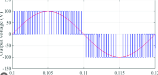
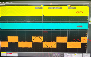
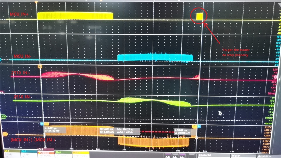
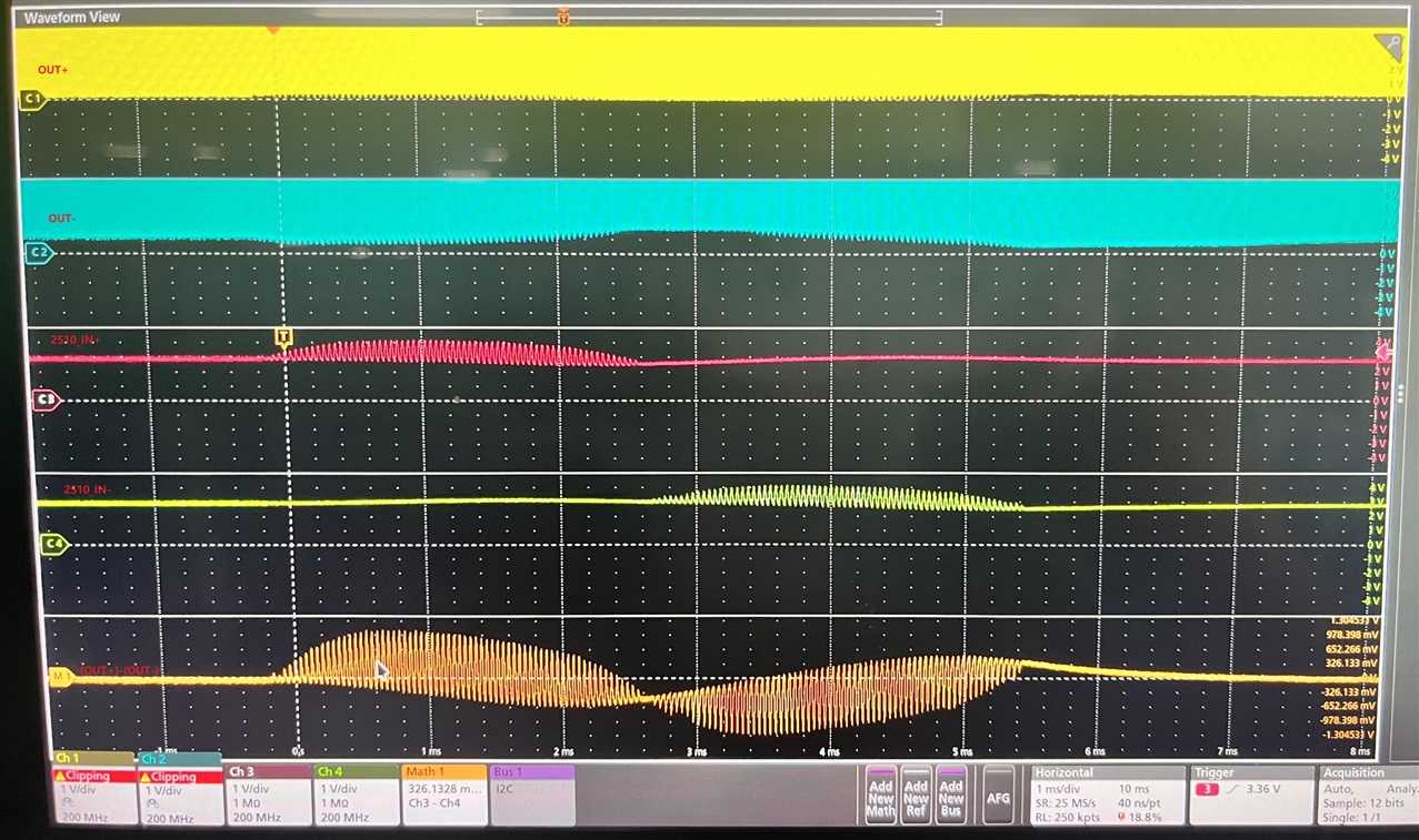
The motor requires a sine wave control signal of 160~200Hz 12Vrms.

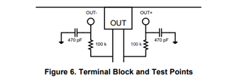
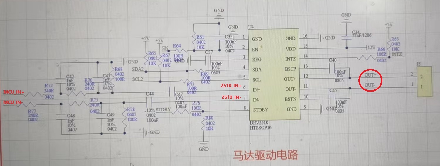
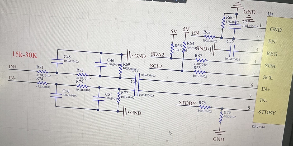
Our schematic diagram is as follows:

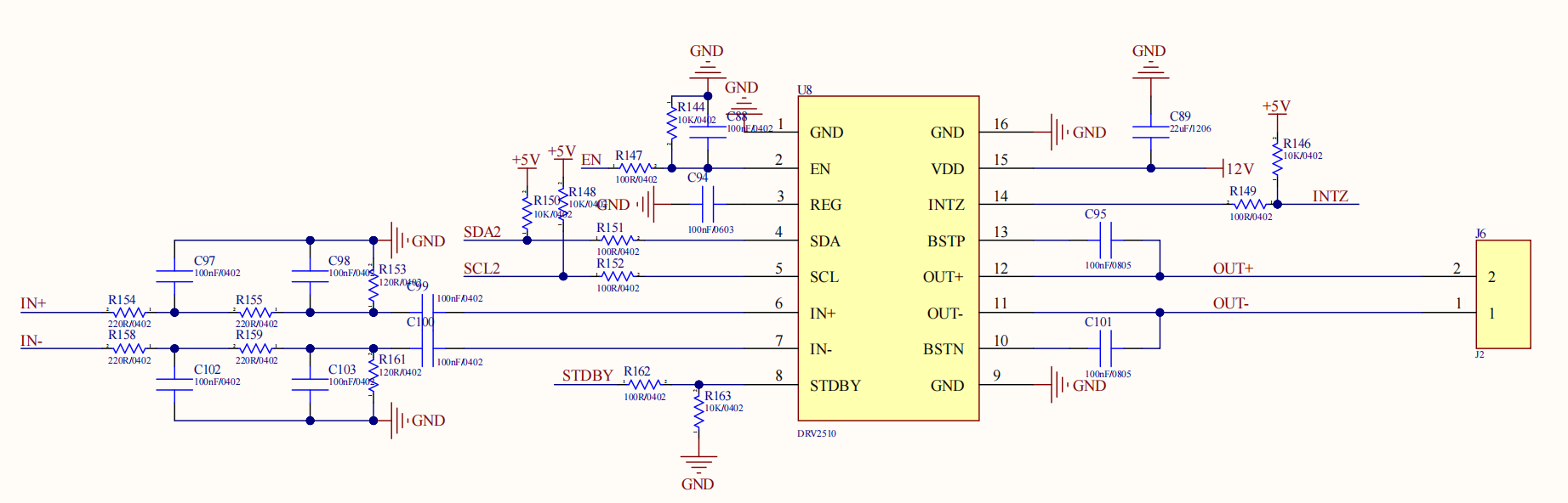
We tried to configure 0x03 00h(20dB 400KHz) mode, but failed.

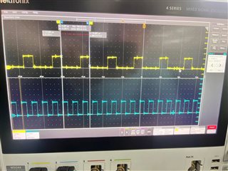
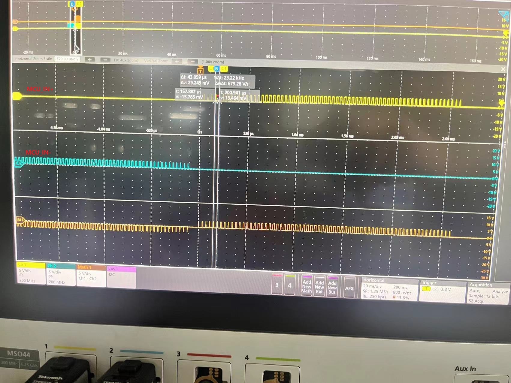
How should we configure the input PWM IN+/- from MCU 5V PWM? Is the LPF circuit need to be modified?

Best Regards


  • Hello, 

    I am looking into the issue. Please expect a response tomorrow.

    Regards,
    Sydney Northcutt 

  • Hello, 

    Thank you for your patience! I don't notice anything on the schematic right away. I have a few questions to continue here.

    Can you clarify what you mean by fail? Are you not getting an output on OUT+ and OUT-? 

    Does a fault trigger?

    Regards,
    Sydney Northcutt 

  • Hi 

    For example, we input a 180Hz PWM signal, which is send to the IC after LPF.

    The output out+,out- is always a 400kHz square wave, not a sine wave.

    At the same time, observe the waveform of (out+)-(out-), as shown in the figure below.

    This is not what we expected, we wanted to get a sine wave output signal.

    How do we achieve 180Hz sine wave output?

  • Hi Tommy, 

    I believe the below excerpt from the EVM user guide will be helpful. Depending on what you are using, you could add the filter on your scope. 

    Regards,
    Sydney Northcutt 

  • Hi Sydney,

    We try to add the filter on the scope, but we don`t know if it works.

    Because we failed to input a sine wave for DRV2510.

    The parameters of our LPF should be incorrect. Could you please provide suggestions for the LPF?

    What value should we change the resistance and capacitance to? (The MCU provides a 180Hz square wave)

    Thanks!

    Best Regards

  • Hi Tommy, 

    Understood. Please expect a detailed response this afternoon.

    Regards,
    Sydney Northcutt

  • Hi Sydney,

    Thanks a lot!

    We look forward to your support!

  • Hi Tommy, 

    Thank you for your patience. I first want to clarify that you will not see an analog / sine wave output from DRV2510 as it is a class D amplifier. It will be a sine wave but in PWM format at the oscillation frequency, which is the carrier frequency (400kHz or 500kHz). The PWM signal will change duty cycles to represent a sine wave. The image below may be helpful. The blue signal is what you would see on the output, but the red signal is what would be seen by the load as solenoids / voice coils have a LPF structure in their composition. 

    To actually convert the PWM signal to an analog signal for measurement purposes, a LPF will be needed on the output. We have the below set up on the EVM. 

    This is an analog input device so a low pass filter is needed after the after the input PWM signal but a PWM signal will be seen on the output. It seems this is already the signal that you are seeing on your output. If you zoom in, you should see a varying duty cycle. That being said, I think your input LPF is okay but we can evaluate it further. Can you take scope screen shots of the input signal after your input LPF?

    Regards,
    Sydney Northcutt 

  • Hi Sydney,

    The input signal as follow:

    Thanks

  • Hi Tommy, 

    Can you show on your schematic where these measurements were taken? This seems like yellow is the input signal and blue is the output signal. Is this correct? Can you measure and show the input signal pre LPF and the input signal post LPF? 

    You mentioned 180 Hz previously, but it seems you are inputting 180 kHz? 

    Regards,
    Sydney Northcutt 

  • Sorry we're a little late with the update.
    Recently, we have made some attempts, but there are still problems.
    Here are the latest SCH:

    We have passed the algorithm, let the MCU output a PWM modulation waveform, so as to produce a 180Hz SPWM as far as possible.
    The waveform we measured is as follows:

    There are two main problems at present:
    1. Can the waveform received by DRV2510 be closer to a sine wave by modifying the parameters of LPF? Please provide LPF parameters.
    2. We found that when 2510_IN has no signal input, there is still an output in the output waveform of DRV2510 ("? "in the figure). Annotated). Why does this happen? How to correct it?

    BR

  • Hi Tommy,

    To confirm, your input is 180kHz PWM and you are wanting to see the PWM equivalent of a 180Hz sine wave on the output, correct?

    1. You can change R70, R72, R75, and R77 to 24kohm to decrease to cut off frequency to about 6kHz. Does this cut off frequency work for your application? 

    2. Does this only happen after a signal is applied to the inputs?

    Regards,
    Sydney Northcutt 

  • Hi Sydney,

    Q1.We can change the input to achieve this result that"you are wanting to see the PWM equivalent of a 180Hz sine wave on the output".

    In fact, The input is about 23~24KHz.

    We tried change R70, R72, R75, and R77 to 24kohm.

    Although it did not meet expectations, it had a certain impact on the waveform.


    We finally tried to modify the circuit parameters, as shown in the figure below:

    If there are other LPF parameters for reference, we will continue to test.

    Q2. The error output (marked '? '), happens only at the end of each signal.

    And when we test, whether the output is connected to the load or not, there will be this error output (marked '? ').

    And the error output(marked '? ') always shows a negative output value for about half a cycle (180Hz).

    We are now also trying to solve Q1 on our own.

    However, we do not know the cause of Q2 and we cannot eliminate it. Please pay special attention to Q2.

    Thanks a lot!

  • Add:

    The output waveform measured after the updated circuit parameters is as follows:

  • Hi Tommy, 

    The filter operation seems odd. Can you remove C47 and C48, and measure the signal before and after the filter? This will essentially disconnect the device so we can just evaluate the filter. Once we solidify the input, we can debug the output issue.

    Also, do you have the EVM?

    Regards,
    Sydney Northcutt