This thread has been locked.

If you have a related question, please click the "Ask a related question" button in the top right corner. The newly created question will be automatically linked to this question.

DRV8874: Current output is chopping (unexpected)

Part Number: DRV8874

Tool/software:

Dear Support Team,

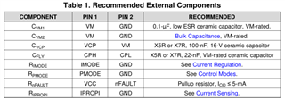
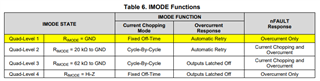
I have configured DVR8874 to be in over-current only fault mode: 

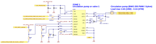
But in the application I see charging of a external elko to look like this:

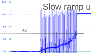
I would expect to not have "current chopping" by my selection of IPROP. 

May it be a problem, that nSLEEP is not driven by some logic, but on 3V3 power-up? Or in other words, can the problem be that the IPROP latching does not work the way I designed it? 

Regards,

Simon

  • Hey Simon, 

    What time scale are you seeing this on?

    And are you PWMing the input signals during this time? 

    Can you confirm that the values of the charge pump capacitor C601 and C_FLY (C602) match our external components table? 

    Also can you clarify what "charging of a external elko" means?  Just trying to make sure I know where this measurement was taken

    Best,

    Jacob

  • Dear Jacob,

    thanks for reaching out.

    I can confirm, CPump and CFly are X7R of rated value.

    No, the input-signals are static, no PWM.

    The external capacity is 1000µF, the timescalce is 100ms / div. The measurement is taken at the 1000uF cap with a cable of 1m between the two boards.

    If I assemble L600 and remove R601, the output is rising high as expected.

    C612 is 10uF.

    Regrads,

    Simon

  • Hey Simon,

    Ahh okay interesting, thanks for the details.

    If I assemble L600 and remove R601, the output is rising high as expected.

    The L600 shouldn't be necessary here. The inductor opposes rapid changes in current so it could explain the slow rise, though I would have thought R601 would make the current "skip" the inductor and it be ignored.  

    What happens if you just install R601 (0Ω) and remove L600?  

    can the problem be that the IPROP latching does not work the way I designed it? 

    Can you elaborate your concern? I don't see an issue with the IPROPI setup - the capacitor parallel with IPROPI resistor is fine, good to filter out spikes. 

    Best,

    Jacob

  • Hey Jacob,

    The L600 shouldn't be necessary here. The inductor opposes rapid changes in current so it could explain the slow rise, though I would have thought R601 would make the current "skip" the inductor and it be ignored.  

    Slight smile I hope so very much!!! Right now we produce with the inductor assembled and the resistor removed. I really want to understand why we need the inductor, as I agree, it should not be necessary from the datasheet.

    Can you elaborate your concern? I don't see an issue with the IPROPI setup - the capacitor parallel with IPROPI resistor is fine, good to filter out spikes. 

    Ah, typo. I want to say IMODE latching. It seems like the chip is in current chopping mode, isn't it?

    Regards,

    Simon

  • Hi Simon,

    It looks like the schematic configuration with RMODE tied to GND, the Overcurrent Response is in the Automatic Retry state. 

    In this state Current Chopping is set for a Fixed On Time but nFAULT Response is set for Overcurrent Only.

    Best,

    David

  • And in that case I can skip tOFF by reenabeling via IN1/IN2. This will charge the cap faster. But only if the cap has a reverse voltage/current protection diode.

    Am I right with this assumptions?

    Another related question:

    To enforce longer current output in my application I would like to connect nFAULT to IPROP to have the IPROP pin cap discharged. Then I have longer time of current flowing until trip point. I that a good idea, or do you have concerns?

    Regards,

    Simon

  • Hi Simon,

    There are two current regulation modes on this device. First is a fixed off time, the second is a cycle by cycle off time and during both of these off times the outputs are disabled until the current falls below the set trip threshold. It is not recommended to try to skip this time. This off time is crucial for the load current to decay and recirculate through the device. 

    What is your load?

    How much current do you need to draw and for how long?

    It would be more suitable to pick from some of our motor drivers that can offer a higher RMS current threshold. 

    Best,

    David

  • Hi David,

    nFault is a bad idea, I see.

    In one uscase I have a 1000µF cap to charge up to 12V. This will take 2.4 ms with 5A trip current and toff skipped by reading nFault as interrupt and reenable IN. I wonder if C612 should be of high or low value to make this happen smoothly. From your answer I read that nFAULT will keep beeing present if IPROP pin discharges slowley. What do you think?

    Best,

    Simon

  • Hi Simon,

    I will discuss this setup with my team and get back to you tomorrow. 

    Best,

    David

  • Hi Simon,

    I have a few follow up questions to better understand your design. 

    What is the desired outcome to be achieved by skipping tOFF?

    Is C612 off IPROPI equal to 1000uF? We generally see this configuration in automotive setups to bypass the ITRIP threshold to guarantee the OCP triggers before ITRIP. If ITRIP is not necessary, why not disable the ITRIP functionality?

    Not sure what part of circuit is being charged up to 12V?

    What do you mean high or low value of the capacitor?

    Best,

    David

  • Dear David,

    after reviewing the datasheet in all details and some work in the lab, I come to the conclusion, that this chip is not suitable to drive a big capacitive load. I will choose a different chip.

    Thank you,

    Simon