This thread has been locked.

If you have a related question, please click the "Ask a related question" button in the top right corner. The newly created question will be automatically linked to this question.

MCF8316A: Motor is not spinning without uC

Part Number: MCF8316A
Other Parts Discussed in Thread: , MSP430FR2355

Tool/software:

Hello,

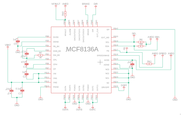
I have a question about MCF8316A. I want to use it without any uC. I made the diagram exactly as in the example from the data sheet as you can see in the picture above [R8, R9, R10, R11= 5.6koHm ]. The brake is connected to GND externally trough a 10k resistor and the Direction pin is connected to AVDD trough a 10k resistor. I have all the necessary voltages: AVDD=3.3V; DVDD=1.5V; Buck/LDO regulator in resistance mode=5V; CP=17V (VM=12V). I also plugged in the BLDC motor, a drone one [DJI mini-3], but is not spinning. What else should I do in this situation to spin the motor?

  • I want to specify that I apply an analog voltage between 2.3-3V to the speed pin

  • Hi Vinsch,

    Have you configured/tuned the MCF8316A registers for your motor? The MCF8316A requires some basic tuning in its register settings, specific to your motor, before you can spin up the motors.

    If you are to use it without an external microcontroller, then the register settings need to be programmed into the device's internal EEPROM register memory so that they will be loaded on power-up. The registers can be configured/programmed using I2C (see datasheet section 7.6 EEPROM access and I2C interface).

    These basic essential settings include:

    • Motor Parameters
      • Motor Phase Resistance [MOTOR_RES]
      • Motor Phase Inductance [MOTOR_IND]
      • Motor BEMF Constant [MOTOR_BEMF_CONST]
      • Speed Loop Kp [SPD_LOOP_KP]
      • Speed Loop Ki [SPD_LOOP_KI]
      • If a speed command is given while any of these 5 parameters above are 0, then device will automatically attempt to run it's built in Motor Parameter Extraction Tool (MPET) algorithm to measure these values.
      • If MPET fails to measure these values, you may need to enter these parameters manually. See this E2E FAQ for more details.
    • Maximum Speed [MAX_SPEED]

    There are many other register settings that you'll want to tune and optimize for your motor/application, such as various current limits, acceleration rates, fault configs etc.

    Please refer to the MCF8316A Tuning Guide for instructions on how to tune various parameters.

    Regards,
    Eric C.

  • Hi, so I tried to program the registries as you said [using Arduino UNO] and I used this code that I found on a forum:

    #include <Wire.h>


    const int deviceAddress = 0x01;


    void setup() {

      int error, n;


      Wire.begin();

      Wire.setClock(50000);      // 50kHz, half the normal speed


      Serial.begin(115200);

      Serial.println("Starting");


      // ------------------------------------------------

      // Write data to a register

      // ------------------------------------------------

      const byte control_word1[] = {0x02, 0x50, 0x00, 0x8A}; // <--- set the right numbers

      const byte data1[] = {0x00, 0x00, 0x00, 0x00};   // <-- set the right numbers


      Wire.beginTransmission(deviceAddress);

      Wire.write(control_word1, 3);

      Wire.write(data1, 4);

      error = Wire.endTransmission();

      if(error == 0)

      {

        Serial.println("Data succesfully sent");

      }

      delay(1);               // the chip needs some time ?


      // ------------------------------------------------

      // Read data from a register

      // ------------------------------------------------

      const byte control_word2[] = {0x02, 0x50, 0x00, 0x8A};  // <--- set the right numbers


      Wire.beginTransmission(deviceAddress);

      Wire.write(control_word2, 3);

      error = Wire.endTransmission(false);   // 'false' for a repeated start

      if(error == 0)

      {

        Serial.println("Register succesfully selected");

      }

      delay(1);               // the chip needs some time ?


      n = Wire.requestFrom(deviceAddress, 4);

      if(n == 4)

      {

        Serial.println("Data received");

        for( int i=0; i<4; i++)

        {

          Serial.print("0x");

          Serial.print(Wire.read(), HEX);

          Serial.print(", ");

        }

        Serial.println();

      }

      delay(1);               // the chip needs some time ?

    }


    void loop() {}

    Could you please check if it's good? I don't really know how to form the control word for writing values in closed loop2, 3, 4 for motor_res, motor_ind, motor_bmef, speed_loop_kp, speed_loop_ki. What values should these last 2 parameters have [speed_loop_kp, speed_loop_ki]?

  • Hi Vinsch,

    Just want to confirm that you don't have a MCF8316AEVM correct? The EVM + GUI is probably the easiest way to configure/tune the device registers for your motor.

    Regarding to your Arduino code, I'm not sure, but the Wire.write() command probably sends the start condition along with the target address and R/W bit automatically, so you might only need to provide the 24-bit control word. Also, I would set CRC_EN to 0 to avoid needing to calculate/transmit the additional CRC byte. So I would try changing your control_word1[] = {0x100x00, 0x8A};

    You can also refer to this E2E FAQ on using a MSP430FR2355 LaunchPad to program/communicate with the MCx devices using I2C:
    https://e2e.ti.com/support/motor-drivers-group/motor-drivers/f/motor-drivers-forum/1246892/faq-program-mcx-bldc-motor-driver-through-i2c-using-msp430-launchpad

    Using the example project for MSP430FR2355 LaunchPad, you should easily be able to modify the code to read/write to any registers in the MCF8316A device.

    Regards,
    Eric C.

  • Hi Vinsch,

    Could you please try the following code on your Arduino:

    #include <Wire.h>
    
    void setup()
    {
      Serial.begin(115200);
      
      Wire.begin();
      Wire.setClock(100000);
      
      read32(0x80);  // 32-bit read register 0x80
      write32(0x80, 0x12345678);  // 32-bit write  to register 0x80
      read32(0x80);  // 32-bit read register 0x80
    }
    
    void loop()
    {
    }
    
    void read32(int reg_addr)
    {
      byte reg_addr_H = (reg_addr & 0x0F00) >> 8;
      byte reg_addr_L = (reg_addr & 0xFF);
      
      const byte control_word[] = {0x90, reg_addr_H, reg_addr_L}; // 24-bit control word (CRC_EN = 0)
     
      Wire.beginTransmission(0x01);
      Wire.write(control_word, 3); // send the control word
      Wire.endTransmission();
    
      Wire.requestFrom(0x01, 4);    // request 4 bytes (32-bit read)
    
      unsigned long register_value = 0;
      for (int i = 0; i < 4; i++)
      {
        unsigned long c = Wire.read(); // receive a byte as character
        register_value |= (c << (i * 8)); // reconstruct 32-bit value (LSB is received first)
    //    Serial.println(c, HEX);         // print each received byte
      }
      
      Serial.print("Finished reading register: 0x");
      Serial.println(reg_addr, HEX);
      Serial.print("Value = 0x");
      Serial.println(register_value, HEX);
    }
    
    void write32(int reg_addr, unsigned long writedata)
    {
      byte reg_addr_H = (reg_addr & 0x0F00) >> 8;
      byte reg_addr_L = (reg_addr & 0xFF);
      
      const byte control_word[] = {0x10, reg_addr_H, reg_addr_L}; // 24-bit control word (CRC_EN = 0)
      byte data[] = {0x00, 0x00, 0x00, 0x00};   // 32-bit register data to be written
     
      for (int i = 0; i < 4; i++)
      {
        data[i] = ((writedata & (((unsigned long)0xFF) << (i * 8))) >> (i * 8));
      }
     
      Wire.beginTransmission(0x01);
      Wire.write(control_word, 3); // send the control word
      Wire.write(data, 4);  // send the 32-bit write data
      Wire.endTransmission();
    
      Serial.print("Finished writing to register: 0x");
      Serial.println(reg_addr, HEX);
    }

    I created a simple read and write functions and verified that they work on my MSP430FR2355 LaunchPad

    Regards,
    Eric C.

  • Hello Eric,

    Yes I don't have the EVM Board

    I tried the code and this results in the serial monitor:

    Finished reading register: 0x80
    
    Value = 0x12345678
    
    Finished writing to register: 0x80
    
    Finished reading register: 0x80
    
    Value = 0x12345678


    What should I do next? Can you please make this code to change the necessary parameters ?
    (motor_res, motor_ind, motor_bemf, speed_loop_kp, speed_loop_ki)
    in the registers ClOSED_LOOP2, CLOSED_LOOP3 and CLOSED_LOOP4?

    I understood from the datasheet that the addresses are 0x8A; 0x8C; 0x8E

    In the end I just want the motor to spin or at least have some feedback on the phases to be able to measure it

  • Hi Vinsch,

    I would highly recommend using an EVM to tune the device registers for your motor since the GUI makes it easy to change the register settings. However, you can achieve the same tuning by using a standalone microcontroller by following the tuning guide.

    Please refer to Chapter 3 Essential Controls in the MCF8316A Tuning Guide:

    1. Ensure zero % speed command is applied on your SPEED pin
    2. Write the recommended default values into all corresponding registers from Table 3-1 in the tuning guide
    3. Configure [MAX_SPEED] based on your motor/application's max speed
    4. Configure [ILIMIT] based on your motor's rated peak current
    5. Clear any potential existing fault by setting the [CLR_FLT] bit in the [DEV_CTRL] register (address 0xEA)
    6. Apply a non-zero speed command
      1. this will automatically trigger MPET, since MOTOR_RES, MOTOR_IND, MOTOR_BEMF_CONST, SPD_LOOP_KP, SPD_LOOP_KI are 0
      2. MPET will spin up the motor while measuring BEMF and speed Kp/Ki, so make sure to clamp your motor down.
    7. If MPET completes successfully, you'll see the motor slow down briefly, then spin up again to the previously commanded non-zero speed.
    8. Stop the motor by applying zero speed command
    9. Read back all registers and manually save the value somewhere
      1. You can check the motor parameter registers to see the values that MPET measured
    10. Trigger a EEPROM write by writing 0x8A500000 into the [DEV_CTRL] register (address 0xEA)
      1. This will copy the register values from the device's "shadow register" memory region into the EEPROM register memory region, so that the register settings are retained across power cycle.

    FYI, when you send I2C commands to the MCF8316, you are reading/writing into mirror-copies of the EEPROM registers that we call "shadow registers", which reside in RAM and directly affect the motor control algorithm's behavior. However, these values are not retained across power cycle, so if you change some register settings and want the settings to stick through power-cycles, then you'll need to write the values from the shadow registers into the EEPROM registers. Below is an overview of what the register memory looks like

    Regards,
    Eric C.