Other Parts Discussed in Thread: DRV10964, MCF8315C,
Tool/software:
Dear technical team,
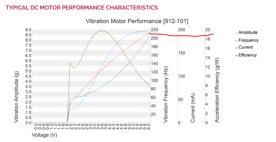
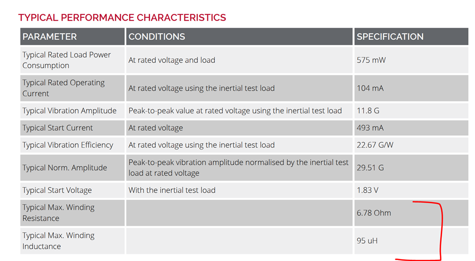
I am using the 912-101 motor from precision microdrives. The motor is connected to three dedicated ports. The issue is it is exactly the same in the E2E thread, but I did not manage to enter to closed loop operation because I don't understand what i have to do on the config test point.
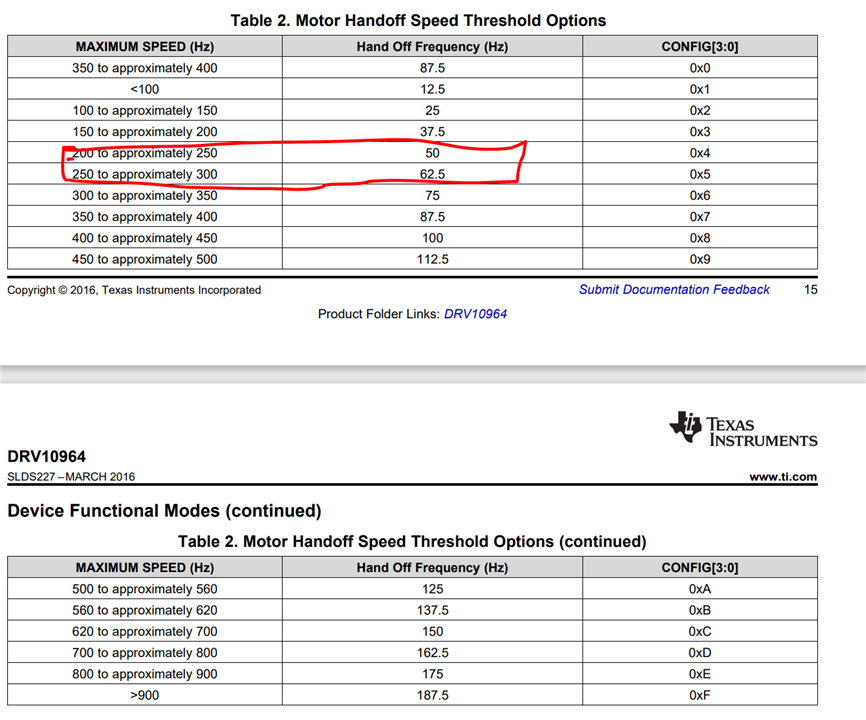
When I apply the supply voltage on the J1 connector, the motor behavior is the same as on the video on the forum topic issue. But as explained by one of the technical agents on the above linl, it is a normal behavior, as the board needs a particular voltage on the CONFIG pin to enter in a closed loop operation. This particular voltage is calculated using the formula described in the forum topic and might be determined empirically.
If I understand well, I have two ways for tuning this voltage :
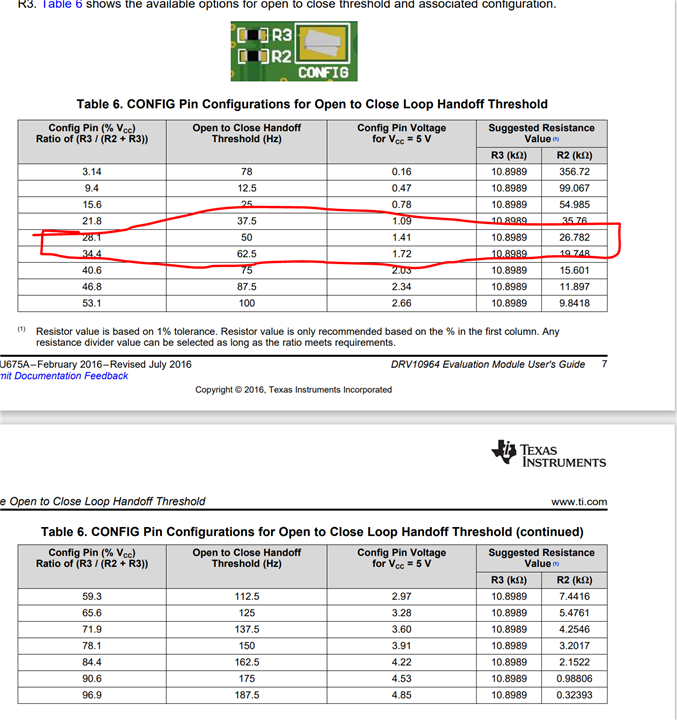
- Change the resistors R2 and/or R3 to get the adapted voltage, according to the table 6 on the datasheet of the board.
- Change the voltage on the CONFIG test-point.
I don’t understand the last point : how do I change the voltage ? Do I have to apply the adapted voltage between the config test point and the ground using a second power supply ?
I just notice on the picture that there is not any R2 resistor on the board. Is this critical ?
I thank you in advance for your answer.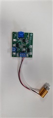
Joris