This thread has been locked.

If you have a related question, please click the "Ask a related question" button in the top right corner. The newly created question will be automatically linked to this question.

DRV8706-Q1: Spice Model

Part Number: DRV8706-Q1
Other Parts Discussed in Thread: DRV8701

Tool/software:

Hi team,

I have a customer that is asking for the Spice model of the DRV8706, since on the 8706 webpage it's only showing the 8701. Curious to know what's going on there, thanks in advance for the help!

Marco

  • Hey Marco,

    That's odd, thank you for bringing that to our attention - I'm not sure why the 8701 SPICE model is showing up on the 8706 page 

    Unfortunately, the DRV8701 model is the closest thing we have to a SPICE model for this part.  I checked our system to make sure we didn't link it wrong, but nope the DRV8701 is all we have. 

    You can see 8.2.2 Detailed Design Procedure in the datasheet for some calculation help like VCP Load, IDRIVE calculation, Current Shunt Amplifier config, and Power Dissipation.  

    Best,

    Jacob

  • Hi Jacob,

    I have a follow-up from the customer who wants help with configuration of the EVM. See the full details below and let me know if you can help here

    "I’m seeing something peculiar that I am having trouble pinpointing the source of the issue to.

    We’re running in mode 3 and am seeing the full positive to minus voltage swing across the motor. I’ve sniffed the eval kit and that confirmed our board + firmware is doing something wrong. I’ll attach a couple scope and logic analyzer shots of what I’m seeing.

    motordriverschematic.pdf

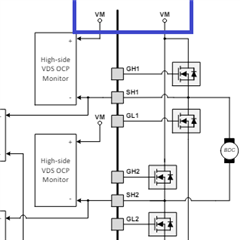
    Here I’m manually toggling our IN1 and IN2 to see which gates are being turned on and it appears that if either IN1 or IN2 are low, the bridge has both low sides high and the high sides low. This made me think that either I’m in the wrong mode, but by depopulating the MODE resistor completely, it still behaves the same unfortunately.

    in1_in2_toggle.pdf

    The two oscope shots below have a diff probe across the motor terminals and a current probe on the positive side of the motor. Ignore the absolute diff probe voltage as it’s not scaled right.

    Using the same configuration (mode 3, PWM @ 75%) our board shows this:

    own_board_scopeshot.pdf

    The evm shows:

    evm_scope_shot.pdf

    So I can see the TI EVM is what I would expect and follows the truth table in the datasheet.

    I sniffed the gate and in1/2 on the EVM to verify:

     in1_in2_evm.pdf

    So I can see that the PWM needs to inverted on ours (which is what I just tried to see that didn’t fix the problem). So with our PWM inverted, I would have expected to follow the truth table, but something is not correct.

    I’m happy to provide you with the raw data, schematics, board files, etc. Didn’t want to overwhelm at first.

    Any idea what’s going on?"

    Thanks in advance!

    Marco

  • Another follow up along with this,

    "Forgot to include the zoomed in on our board which I think is the sign of something funky with the gate connection perhaps? You can see those little blips in the larger view are the driver trying to do the right thing, but after ~1-2ms the upper gate gets engaged for some reason. If both inputs are 0, I get that the driver is floating the FET gates, but I’m puzzled as to why this is happening when one of the inputs are high?"

    in1_in2_followup1.pdf

    in1_in2_followup2.pdf

    "My current hunch is this is something with the overcurrent protection false triggering. Could you also forward the general question of the correct way to calculate the Vds overcurrent value? My naïve assumption was it’s just the current * FET rds_on or trip current = vds_overcurrent_setting / fet_rds_on = 0.5 / 0.002 = 250A? I feel like I’m missing something obvious.

    The reason this is my hunch is when I remove the load/motor, everything switches as expected. Is it perhaps the EMI cap we have across the motor terminals causing the issue due to the inrush current?"

    "Regarding the problem, I just disabled the VDS overcurrent protection (tied the mode pin to DVDD) and the problem is gone so it does appear to be an inrush current problem. I feel like I have to be misunderstanding how the VDS overcurrent trip value is calculated though as pulling 250A for even a few microseconds doesn’t seem right to me. Is it possible it’s meant to be the sum of the all the resistances between the SH/SL pins? That still puts it in a fishy spot but at least I can squint and see how the traces + sense resistor + 2 rds_on’s could make this in the realm of 10A or so"

  • The customer ended up tracking down the error to being how the firmware is PWMing the inputs, so it's working as expected now. He just wants to know if the way he's understanding the VDS monitor for overcurrent calculation is correct. Let me know what you think!

    Marco

  • Ahh I'm glad they fixed it, interesting! Hmm let me look through all of this, give me another day.  

  • Hey Marco,

    As you say, the VDS protection will trip whenever the VDS voltage is > VDS_LVL, the setting for the trip value.  I agree with you that I think this level should basically be the Current * given fet RDS_ON.  Let me get another coworker to help on this.

    Keerthi/Morita-san, can you help answer the below questions?

    "My current hunch is this is something with the overcurrent protection false triggering. Could you also forward the general question of the correct way to calculate the Vds overcurrent value? My naïve assumption was it’s just the current * FET rds_on or trip current = vds_overcurrent_setting / fet_rds_on = 0.5 / 0.002 = 250A? I feel like I’m missing something obvious.

    The reason this is my hunch is when I remove the load/motor, everything switches as expected. Is it perhaps the EMI cap we have across the motor terminals causing the issue due to the inrush current?"

    "Regarding the problem, I just disabled the VDS overcurrent protection (tied the mode pin to DVDD) and the problem is gone so it does appear to be an inrush current problem. I feel like I have to be misunderstanding how the VDS overcurrent trip value is calculated though as pulling 250A for even a few microseconds doesn’t seem right to me. Is it possible it’s meant to be the sum of the all the resistances between the SH/SL pins? That still puts it in a fishy spot but at least I can squint and see how the traces + sense resistor + 2 rds_on’s could make this in the realm of 10A or so"

    Best,

    Jacob

  • Hi Jacob,

    Thanks for the response! Could you ping Keerthi/Morita-san to also address the questions, please?

    Marco

  • Hi Marco,

    Thank you for your question.

    >>fet_rds_on = 0.5 / 0.002 = 250A? 

    This is correct.

    VDS over current protection may be triggered

    -in case VM is not stable. Then >0.5V bap happens between VM and SH.

    -Or some issue on SPICE Model related. 

    regards

    Shinya Morita