Tool/software:
Hi !
I'm Matis,
An apprentice Engineer, currently working on the design of a power electronics board.
- Context :
We're using a 6-layer PCB, with just over a dozen of the MOSFETs IAUT300N10S5N015ATMA1 from Infineon technologies. The circuit is controlled by a gate driver 2ED21084S06JXUMA1 and operate with a 12V input voltage. These components will generate heat. In normal operation, the board should be able to deliver 120 A continuously. Currently, it delivers only 90 A.
- Problems :
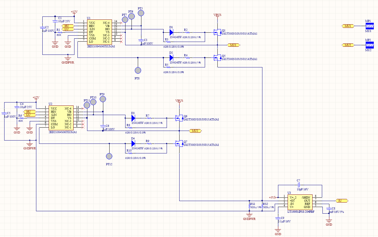
We've noticed that when testing our prototypes, some pairs of MOSFETs in series (in a half bridge configuration) are short-circuited between VBUS and GND (see schematic screenshot), as both MOSFET gates are open at the same time. This Miller Effect could cause cross conduction and could be a reason why our board heats up excessively and doesn't reach the desired voltage.
Our constraints are as follows:
- We have no space on the PCB for a heat sink.
- We can't increase the width of the layers.
- We can't modify the dimensions or shape of the PCB.
- There is no time or space left to route the Mosfets in a different way.
There will still be an aluminum plate under the PCB to absorb heat. We've optimized the heat release as much as possible.
- TPS63710 :
We think that the most appropriate solution is to add a component like the TPS63710 that allows the mosfets to be negatively polarized, to see if this allows us to eliminate the possible cross-conduction and the problems associated with it.
- Question 1 :
We'd like to know if this idea seems viable to you, if you're familiar with this type of solution and what recommendations you could make to design/route the circuit ?
- Question 2 :
- I have found in many similar online circuits that the addition of Cgd, Cgs and Cds capacitors can greatly improve the stability of this type of MOSFET half-bridge circuit, by mitigating fast switching effects such as the Miller effect and voltage transients. In my case, this could be relevant.
- I've also noticed that using an RLC circuit at the output of a MOSFET half-bridge is an effective technique for handling fast switching problems.
Are these methods useful? or even compatible with the addition of TPS63710?
Thank you in advance for your help !
Arm 1 3D exemple :

Miller effect :

blue is the voltage sent to the motor, red the high-side switching, green the low-side switching and purple the current drawn by the board. The miller effect can be seen on the falling edge of the low side.
Arm 1 schematic :