This thread has been locked.

If you have a related question, please click the "Ask a related question" button in the top right corner. The newly created question will be automatically linked to this question.

DRV8243-Q1: DRV8243-Q1 library with SPI commands

Part Number: DRV8243-Q1

Tool/software:

Hi, 

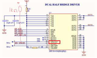
We are currently using the DRV8243-Q1 SPI(S) variant (DRV8243SQDGQRQ1) connected to the seeeduino xiao nrf52840 board.

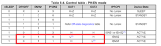
The nSLEEP pin is always pulled high in the hardware and DRFOFF, EN/IN1, and PH/IN2 are not connected to the Seeduino Xiao board. We are aiming to have the DRV8243 in PH/EN mode and control based on SPI commands.

Attaching our current code to drive the DRV8243 to have the following states and the hardware connection:
1) OUT1 as low and OUT2 as High with SPI_IN register's bits S_DRVOFF,S_EN_IN1,S_PH_IN2-> 010 and
2) OUT1 as high and OUT2 as low with SPI_IN register's bits S_DRVOFF,S_EN_IN1,S_PH_IN2-> 011

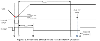
Not able to get the desired outputs in the OUT1 and OUT2 lines despite the CLK, CS, and MOSI lines transferring the data bits to the appropriate register address. We were able to read the device ID as 32h for the DRV8243S-Q1 device from the DEVICE_ID register (Address = 00h) if using SPI_MODE0.

We got a decimal value of 129 from the FAULT_SUMMARY Register (Address = 01h) [reset = 40h] even when writing to command register [write8(0x08, 0b10000000);]


Could you please help in reviewing the code and let me know if I am missing anything? 

#include <SPI.h>
#include <Adafruit_TinyUSB.h>  // for Serial
#include <Arduino.h>
#include <Wire.h>
#include "DRV8243.h"

DRV8243 hbridge;

void setup() {
  Serial.begin(115200);
  hbridge.begin();
}

void loop() {
  //PH/EN state to have outonelow_outtwohigh
  int seconds = 50;
  hbridge.outonelow_outtwohigh(seconds);
  hbridge.drive_nocurrent();
  delay(5000);
  seconds = 5;
  hbridge.outonehigh_outtwolow(seconds);
  hbridge.drive_nocurrent();
  delay(1000);
}
 

 DRV8243.cpp   

DRV8243.h

Thanks for your help.


  • Hi ,

    Thank you for your questions.

    >>Not able to get the desired outputs in the OUT1 and OUT2

    1)Could you describe what you saw on OUT1 and OUT2? As you mentioned, you are expecting OUT1, OUT2 = Low and High or High and low. Could you inform what you saw for each case.

    2)Secondary, your supply voltage and nSLEEP connection could not be correct. nSLEEP operation max voltate is 5.5V. What is the voltage level of V6V5? 

    What is your SPI/MCU voltage level? I suggest to apply 5V or 3.3V on nSLEEP pin which is matching to SPI logic level comes from you MCU.

    3) Could you add external pull up resiter (1Kohm) to 5V? Then check whether nFAULT is high? If it is low, device has some fault condition.

    regards

    Shinya Morita

  • Hi Shinya,

    Thanks for your answers.

    1)"Could you describe what you saw on OUT1 and OUT2? As you mentioned, you are expecting OUT1, OUT2 = Low and High or High and low. Could you inform what you saw for each case."

    Ans: You are correct. We are looking for the states that you highlighted.

    With the current code setting and board (with nSLEEP still receiving 6.5V), we have the following results:

    The motor connected between OUT1 and OUT2 did not work for both conditions.

     Using the function outonehigh_outtwolow(seconds) and outonehigh_outtwolow(seconds), I get ~300mV on OUT1 and OUT2

    The fault, status, and status 2 registers show (Note: while measuring we did not connect the load):

    “Fault Register: 129

    Status1 Register130

    Status2 Register131”

    Note:

    If I increase the current clock SPI settings to 10MHz from the current 4Mhz, outonehigh_outtwolow(seconds) showed ~0.4V on both pins whereas the other function, still resulted in ~300mV

    2. "Secondary, your supply voltage and nSLEEP connection could not be correct. nSLEEP operation max voltate is 5.5V. What is the voltage level of V6V5? 

    What is your SPI/MCU voltage level? I suggest to apply 5V or 3.3V on nSLEEP pin which is matching to SPI logic level comes from you MCU."

    Ans: For question 2, we are currently working to connect the nSLEEP pin to 3.3V and ours is a 3.3V logic level board.

    3. "Could you add external pull up resiter (1Kohm) to 5V? Then check whether nFAULT is high. If it is low, device has some fault condition."

    Ans: When connected to the external 5V supply and a common ground to the board,  the nFAULT pin had measured high (5V).

    Note: nSLEEP was still receiving 6.5V

    Could you please review the code for the SPI_ERR as well? 


  • Hi,

    Thank you for your feedback. Let me feedback to you today.

    regards

    Shinya Morita

  • Hi,

    Looks like OUTPUT is not working. Customer code is complicated firmware program, I cannot find what is not correct.

    My suggestion is to try follows as simple test.

    1) Disconnect load from OUT1 and OUT2. (OUT1 and OUT2 are open)

    2) Supply VM=12V. nSLEEP=High input (3.3V or 5V). DRVOFF=Low (0V).

    3) Check nFALUT voltage with 1Kohm register. (nFAULT should be 0V now. If not 0V, something is wrong)

    4) Write 91h(1001 0001) on Addr=08h. (CLR_FLT, SPI_IN_LOCK= unlock)

        Read DRVICE ID(addr=00h), then read data should be 32h. (If not, SPI communication is not correct)

        Read FAULT Summary (addr=01h). Then read data should be 00h or 40h. (If not, please let us know what is the reading value)

        Now nFAULT pin should be changed to High as Fig 7-9

    5) Write 0Eh(0000 1110) on Addr=09h(SPI_IN_register. S_EN=1 and S_PH=0).

        Now Out1 = ~0V and OUT2 = VM (~12V). 

    If 1)-5) is OK, possible to try with load connected. Then I think motor should start spinning. 

    regards

    Shinya Morita