This thread has been locked.

If you have a related question, please click the "Ask a related question" button in the top right corner. The newly created question will be automatically linked to this question.

DRV8212: DRV8212 VM Pin Function and Power Supply Setup

Part Number: DRV8212
Other Parts Discussed in Thread: TPS62933, DRV8220

Tool/software:

Hi everyone,

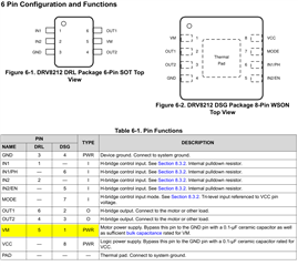
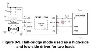
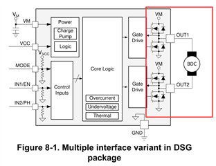
I'm working on a project that controls a 12V DC motor using a DRV8212 driver IC. The motor needs to run forward and backward based on commands from an MCU (Microcontroller Unit). I'm planning to use a PWM channel for speed control.

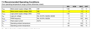
I've been reviewing the DRV8212DSGR datasheet and understand the functions of most pins. However, I'm unclear about the VM pin. There seems to be some confusion online about its purpose.

Here's my specific question:

Is the VM pin on the DRV8212:

  • A voltage monitoring pin?
  • A power output pin (if so, what's the input voltage source)?
  • A power input pin (the datasheet mentions VCC for power supply)?

I'm using the DSB package of the DRV8212DSGR, which also has a VCC pin for power supply.

Additional Information:

  • My main power source is a 16V-20V battery. I'm using a TPS62933 buck converter to regulate the voltage down to 12V for both the motor driver and the MCU.
  • The MCU is powered by a separate 3.3V supply from a master board. The MCU acts as a slave device that controls the motor.

My Question:

Do I need to connect anything to the VM pin? Should I leave it floating, or connect it to the 12V output from the buck converter?

I appreciate any clarification and guidance on this topic. My project deadline is approaching, and I'd like to finalize this aspect of the design.

Thanks & Regards,

  • Hey Dhruvit,

    Apologies for the confusion.  VM is Motor Voltage input for the device.  So in your case you would connect your 12V to the device.  

    See the datasheet:

    You can also check out the EVM to see an example schematic and PCB layout (download the Hardware Files):  https://www.ti.com/tool/DRV8212EVM 

    However, DRV8212 should only be given a maximum of 11V on VM, and typically you should design for a 20% margin on VM for safety.  So I don't recommend using more than 11*0.8 = 8.8V on VM of this device.  

    For a 12V system check out DRV8220 as it is rated for 20V. 

    Best,

    Jacob

  • Hi Jacob,

    Thank you for your previous explanation regarding the VM pin. I'm reaching out again for further clarification on its functionality.

    My Setup:

    • 12V Brushed DC Motor (VCC, GND, Forward, Reverse terminals)
    • 16V-20V Battery (fluctuating voltage)
    • TPS62933 Buck Converter (regulated 12V output)

    Question about VM Pin:

    The datasheet mentions a maximum input voltage of 11V for VM. I'm confused about the purpose of the VM pin since it seems to be both an input and output for the motor voltage.

    Here's my specific question:

    Can I simply connect the regulated 12V output from the buck converter directly to the motor's VCC pin and leave the VM pin unconnected? My concern is that bypassing the VM pin might cause issues with the DRV8212 functionality or damage the motor.

    Understanding VM Pin Functionality:

    • Is the VM pin an input, output, or both for the motor voltage?
    • If it's an input for the DRV8212, how does the DRV8212 utilize the voltage on this pin to control the motor?

    I'd appreciate any insights you can provide. If bypassing VM is not recommended, please suggest alternative approaches, such as adjusting the buck converter voltage or using a different motor driver IC like 

    Hi Jacob,

    Thank you for your previous explanation regarding the VM pin. I'm reaching out again for further clarification on its functionality.

    My Setup:

    • 12V Brushed DC Motor (VCC, GND, Forward, Reverse terminals)
    • 16V-20V Battery (fluctuating voltage)
    • TPS62933 Buck Converter (regulated 12V output)

    Question about VM Pin:

    The datasheet mentions a maximum input voltage of 11V for VM. I'm confused about the purpose of the VM pin since it seems to be both an input and output for the motor voltage.

    Here's my specific question:

    Can I simply connect the regulated 12V output from the buck converter directly to the motor's VCC pin and leave the VM pin unconnected? My concern is that bypassing the VM pin might cause issues with the DRV8212 functionality or damage the motor.

    Understanding VM Pin Functionality:

    • Is the VM pin an input, output, or both for the motor voltage?
    • If it's an input for the DRV8212, how does the DRV8212 utilize the voltage on this pin to control the motor?

    I'd appreciate any insights you can provide. If bypassing VM is not recommended, please suggest alternative approaches, such as adjusting the buck converter voltage or using a different motor driver IC like DRV8220 you said.

    Thanks,

    Regards

  • Hello,

    Can I simply connect the regulated 12V output from the buck converter directly to the motor's VCC pin and leave the VM pin unconnected? My concern is that bypassing the VM pin might cause issues with the DRV8212 functionality or damage the motor.

    What you are describing is Independent 1/2 Bridge control mode, which this device does support but it still needs the motor voltage (12V in your system) on the VM pin.  

    This is basically what you are describing, but note VM needs to be the same on the driver and on the high-side of the load:

    So 12V in this case will still kill the device. 

    • Is the VM pin an input, output, or both for the motor voltage?
    • If it's an input for the DRV8212, how does the DRV8212 utilize the voltage on this pin to control the motor?

    It's an input for the motor voltage.  Then it will go through a FET (think of it as a switch) and be given to OUT1 or OUT2.  See the red section here, think of each FET as a switch:

    Best,

    Jacob

  • Hi Jacob,

    Thanks again for your help with the DRV8220.

    Basic Connections:

    Based on the datasheet, I believe the basic connections are:

    1. Motor VCC to DRV8220 VCC (12V supply)
    2. Motor GND to DRV8220 GND

    Control Mode Confirmation:

    Could you please confirm if the recommended control mode for forward and reverse operation with a brushed DC motor is PWM (IN1/IN2) or Phase/Enable (PH/EN)?

    Connection Details Request:

    While I've reviewed the datasheet for specific pin connections in the chosen control mode, I'd appreciate it if you could provide a quick reference or confirmation for the following connections to control the motor's direction:

    • Forward direction connection (IN1, IN2, PH, or EN pins)
    • Reverse direction connection (IN1, IN2, PH, or EN pins)

    Datasheet Reference:

    I've been referencing the DRV8220 datasheet (link if possible) to understand these connections.

    Learning Experience:

    By providing this information and confirming my understanding, it would be a great learning experience for future projects where I can rely on the datasheet more confidently.

    Thanks again for your support,

  • Hey Dhruvit,

    Could you please confirm if the recommended control mode for forward and reverse operation with a brushed DC motor is PWM (IN1/IN2) or Phase/Enable (PH/EN)?

    You can use either, just follow the datasheet tables for your desired outcome.  PWM will require 2 PWM-capable pins from your MCU for pwm control in both directions.  PH/EN can be thought of as "Direction / Speed" control, so just 1 PWM capable pin is needed to control the speed. 

    While I've reviewed the datasheet for specific pin connections in the chosen control mode, I'd appreciate it if you could provide a quick reference or confirmation for the following connections to control the motor's direction:

    • Forward direction connection (IN1, IN2, PH, or EN pins)
    • Reverse direction connection (IN1, IN2, PH, or EN pins)

    Follow the H-Bridge control tables in the datasheet

    Check out this video, it might help ya:  https://www.youtube.com/watch?v=up5edFaToq4 

    Best of luck, hopefully this helps!

    Best,

    Jacob

  • Hi, Jacob 

    Thanks for reviewing my application, I have connected the PWM pin of MCU to the Motor Signals, as per your suggestion make VM pin a constant between power supply and motor 12v supply, and selected DRV8220 for safer option 

    The motor I don't know working in PWM mode or PH/EN pin but the pin of MCU also work as normal GPIO with internal pull-ups and pull-downs so no worry about that.

    Lastly planned and take reference from EVM module design guide and make schematic if you want to verify then here is the pic of that 

    Thank you for continues support 

    Thanks & Regards

    Dhruvit Bhimani

  • Hey Dhruvit,

    Do you have an oscilloscope or logic analyzer you can use to verify your signals are getting proper voltages?  The pin on your MCU for IN1 (for example) should be set in the MCU as and OUTPUT pin (no internal pull-up or pull-down enabled).  

    Do you have a https://www.ti.com/tool/DRV8212EVM to test with?  

    For the schematic, download the Hardware Files from that EVM page - that will give you the Schematic and PCB layout 

    Best,

    Jacob

  • Hi Jacob,

    Thank you for this most valuable information, about this function I will take care of that and also includes notes in schematic to not trigger internal pull ups and pull-down resistor, although I am also thinking about high impedance gpio level, thanks a lot to clear my doubts.

    Thanks & Regards
    Dhruvit Bhimani