This thread has been locked.

If you have a related question, please click the "Ask a related question" button in the top right corner. The newly created question will be automatically linked to this question.

DRV8703-Q1: About the SO output when the motor is stuck

Part Number: DRV8703-Q1

Tool/software:

Hi Expert,

I am using drv8703 to drive the window lifter and I have a strange problem.

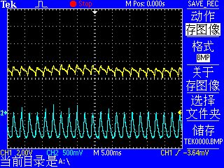
The image on the left shows the SO waveform during normal operation. The picture on the right is the SO waveform when the window is turned to the top.I want to know why the SO waveform of the motor is not a straight level when it is blocked.

Dc brush motor, operating voltage 12V.I want to know if you have any ideas.

BR,

Huan Yin

  • Hi Huan,

    It appears to be the current regulation kicking in. In this case it won't be straight line instead it will be the chopped current waveform. SO waveform will follow the current waveform at SP times the amplification. You can look at the current waveform at SP.

    See below info from the datasheet,

    Regards, Murugavel

  • Hi,Murugavel

    I try to connect the VREF to the AVDD pin to turn off the current regulation but sadly nothing has changed.

    I used a full duty cycle PWM driven DC motor.However, when the motor is blocked, the waveform of the PWM pin will change very strangely.The waveform picture is below.

    CH1 is the PWM pin (IN2), which should be a high level.(CH2 is the motor current measured by the current probe, maybe we can not look at it.)

    I don't understand why IN2 becomes like this when the motor is blocked.Can you help me explain this strange phenomenon?

  • Hi Huan,

    Thanks for the additional info. If 100% duty cycle was used IN2 must stay logic HIGH level. This is input provided by an MCU output pin. I suspect the MCU power supply (from its voltage regulator) may be impacted when the motor is stalled with higher current. You can check the MCU DVDD when the motor is stalled as well a look for any GND loop currents affecting the MCU supply when the motor is stalled. 

    I assume when you said motor was blocked it meant motor was completely stalled and stopped not running with a high load. Please clarify.

    The logic levels on the input pins must comply with datasheet specifications - please see below. A logic low is defined as < 0.8 V and logic high is defined as > 1.5 V. So if the input pin sees a strange waveform input it will be output at the H-bridge.

    When the motor is running normally with nominal load the motor current will be either a positive or negative current super imposed with a sinewave on top of it. The sinewave is a result of back EMF (BEMF) of the motor. The frequency of the sinewave depends on the speed of the motor and the number of magnetic poles in the motor. When the motor is blocked but not stalled to zero speed the BEMF sinewave will still be present but the frequency will be lower assuming the motor was running slower. When the motor is stalled with zero speed the BEMF will also be zero. Now the motor current will be motor voltage VM/ DC resistance of the rotor coil which would be a very high current. Depending on the FET Rdson and the VDS monitor threshold setting you may be able to detect this condition if the voltage across the FET if the (Istall * Rdson) > VDS monitor threshold setting. If the FET Rdson is very low this may not be in proper range to be detected. However the SO can still be used to detect this assuming the sense resistor was properly sized to differentiate between running current peak and stall current of the motor. Thanks.

    Regards, Murugavel

  • Hi, Murugavel

    I'm actually testing a window lifter, which is controlled by a DC brush motor. When I say the motor is blocked, it means that the window goes up to the top and can't go up at all. In fact, I don't know if the motor inside is continuing to rotate, I can only guess that the motor is completely blocked.

    The phenomenon I observed was that the motor blocked transfer caused the voltage of the regulated supply to drop(12V to about 10V) .I wonder if this will affect the waveform.

    BR,

    Huan Yin

  • Hi Huan,

    Thanks for the confirmation. It makes sense it should be completely stalled. 

    The phenomenon I observed was that the motor blocked transfer caused the voltage of the regulated supply to drop(12V to about 10V) .I wonder if this will affect the waveform.

    Yes this will affect the waveform. If the power supply has a current limiting feature that will also affect the waveform. 

    Regards, Murugavel

  • Hi, Murugavel

    I have a guess about that : There are two possibilities when the motor is blocked, which are triggered overcurrent protection of the controller and not triggered overcurrent protection. If overcurrent protection is not triggered, the H-bridge still has output, resulting in waveform errors. I wonder if this guess is correct.

    My power supply current limit value is 5.19A and the VDS control register value is 111 (0.96V). In addition, I also want to know how the configuration value of VDS is calculated as the current value, and where is the relevant formula in the manual.

    BR,

    Huan Yin

  • Hi Huan,

    If overcurrent protection is not triggered, the H-bridge still has output, resulting in waveform errors. I wonder if this guess is correct.

    This may be what was happening. Let's assume the MOSFET you were using had 10 mΩ Rdson. The VDS voltage with 5.19 A would be 0.0519V. If the threshold set was 0.96 V, overcurrent protection will not be triggered.   

    The lowest VDS setting available is 0.06 V. With 10 mΩ Rdson this would translate to 6 A for the OCP current limit. If the Rdson would be much lower than 10 mΩ then the OCP limit for 0.06 V would be even higher current. The formula is Rdson x IOCP = VDS threshold voltage.

    This is in the VDS Configuration section in the datasheet. Thanks.

    Regards, Murugavel

  • Hi, Murugavel

    Thank you for your answer. The Rds(on) of the MOS I used is about 7mΩ, and the VDS protection cannot be triggered under the current limit value of 5.19A.

    Combined with the waveform diagram above, I wonder if this strange IN2 waveform is related to the fact that the H-bridge is not closed? I saw a netizen comment that "the motor makes a sound when it is blocked, indicating that the H bridge has an output and does not trigger overcurrent protection; If the motor does not ring when the rotation is blocked, it indicates that the H-bridge overcurrent protection is triggered." Does that mean that I can avoid this by increasing the current limiting value of the power supply so that the lock-in current can reach the value that triggers the VDS protection.

    BR,

    Huan Yin

  • Hi Huan,

    You said "Does that mean that I can avoid this by increasing the current limiting value of the power supply so that the lock-in current can reach the value that triggers the VDS". Yes this is correct. You must also set the VDS threshold to a lower value and make sure it does not trigger during normal operation but trigger only during stall.

    Regards, Murugavel

  • Hi, Murugavel

    The problem seems to have been solved.I replaced the power supply and set the current limit to 9A and the VDS threshold to 0.06V. Overcurrent protection can now be triggered when the motor is blocked, and the output of SO is also DC high.Thanks again for your answers!

    BR,

    Huan Yin