This thread has been locked.

If you have a related question, please click the "Ask a related question" button in the top right corner. The newly created question will be automatically linked to this question.

DRV8889-Q1: Configuration Issue

Part Number: DRV8889-Q1

Tool/software:

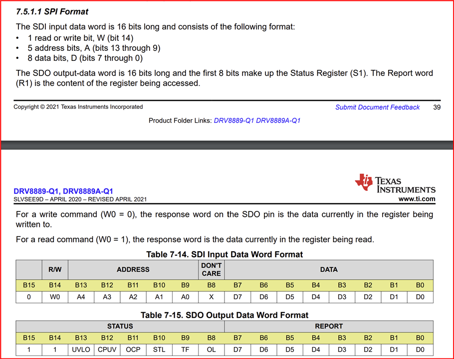
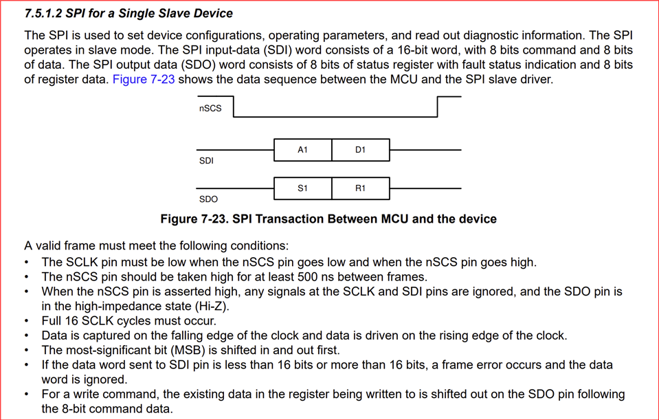
I'm using the DRV8889 IC to drive a stepper motor. I'm unable to get it running , I suspect the format of data sent over SPI is not proper. Could you please provide the format of the data to be sent 

I'm writing the data to the CTRL3 (0x05) register over SPI. Is there any other register to which the data has to be sent over SPI  ?

Also, what should be the ideal voltage at the output pins of the driver IC? Is there any demo code available which I can use as a reference ? 

  • Hi Anusha,

    The format of the data for SPI is provided in the datasheet, see below.

    Also, what should be the ideal voltage at the output pins of the driver IC? Is there any demo code available which I can use as a reference ?

    The voltage peak on the xOUTx pins would be close to the VM voltage applied when the corresponding output is energized. The DRV8889-Q1EVM firmware source code can be downloaded from the EVM webpage, https://www.ti.com/tool/DRV8889-Q1EVM.  

    Please also refer to the attached flow chart. Thank you.

    2867.DRV8889Q1_Stall_Detect_Flowchart.pdf

    Regards, Murugavel

  • Thank you for your feedback, is there any other register to which the data has to be sent or writing to CTRL3 is sufficient? 

  • If you are using an MSP0L1306, there is a driver library available, which can also be used as an example.

  • Hello Anusha,

    Thank you for your feedback, is there any other register to which the data has to be sent or writing to CTRL3 is sufficient? 

    It depends on your application. If you want to enable and use stall detection you have to modify other registers. Please refer to the flow chart.

    With the DRV8889-Q1 you will get the output from the device even without writing to any register (keep all default values) and set the device 'awake' with nSLEEP pin = 1 and DRVOFF pin = 0 for output enable. If you provide STEP input to the pin the driver will drive a stepper motor in full-step mode. It is also important VREF is provided with a voltage for the desired current setting (see datasheet section 7.3.5 Current Regulation. If VREF = 0 the motor will not spin.  

    CTRL3 will allow you to set the microstep mode. If you do not write to this register the driver will operate in full-step mode. After you write CTRL3 register with 0x05 successfully the driver will operate in 1/8 step mode.  

    Regards, Murugavel