This thread has been locked.

If you have a related question, please click the "Ask a related question" button in the top right corner. The newly created question will be automatically linked to this question.

DRV8701EVM: DRV8701EVM

Part Number: DRV8701EVM
Other Parts Discussed in Thread: DRV8701

Tool/software:

Hello,

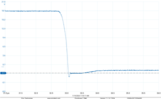
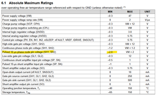
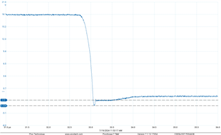
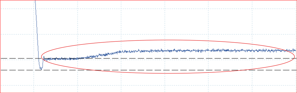
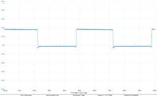
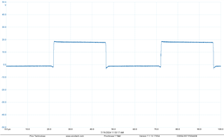
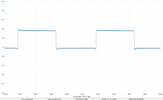
We are using the DRV8701EVM and noticed that the phase node voltage is almost -2V which is close to rated spec which lasts about 50ns. For sub 100ns events is there any relaxed spec or does this apply? This is using the motor at full load.

  • Here is scope plot of what we are seeing. See the spec below

  • Hi Michael,

    Thank you for posting in this forum. The highlighted specification applies for pulses up to 10 us. Please consider the same limit for sub 100 ns pulses as well. These small pulses are expected during dead-time due to inductive kick-back voltage from the motor both above VM (+) and below the GND (-) potential and up to a body diode drop voltage of the output FETs. This should not cause any long term device weakness as long as these spikes don't exceed +/- 2 V w.r.t VM and GND respectively.  

    Regards, Murugavel 

  • Please see the scope plot below. The spikes are exceeding -2V.

    On every pulse we are seeing it go to about -3.30V.
    Is this known behavior or is there something that will fix this issue?


  • Hi Michael,

    Can you please describe what this waveform is and what moment was it captured? For example motor stopped etc. Can we get a few cycles of the output voltage?

    What does the below circled period correspond to? Why there is a shift in the voltage level is what I was curious about. Thank you.

    Regards, Murugavel

  • Hello,

    Sure, let me go into a little more detail. We are stress testing this eval kit to make sure it is robust enough for one of our upcoming designs. We were probing at the phase node voltage at the DRV8701 on the eval kit. The test we performed for this plot was operating a motor under a heavy load at 50% phase voltage. The settings we used in the GUI are pasted down below.
    This curve you highlighted is from this entire plot:


    As for why there is a shift in voltage, I am unsure. Hopefully seeing the whole plot can help you come to a conclusion.

    If you need any more information, please let me know!

  • Hi Michael,

    Thanks for sharing the entire plot. This gives me the context. Those spikes are coming from the inductive kick-back voltage generated by the BDC during the dead-time like I mentioned in the previous post. With your heavily loaded motor these spikes are exceeding the absolute maximum specifications of the driver. So the solution would be to mitigate these spike voltage levels. The reason why it is exceeding the range is because of the body diodes of the FET you're using in not fast enough for this application. A potential solution could be to use fast Schottky diodes for the rated current in parallel with each FET in the H-bridge. Another option may be to use faster MOSFETs (with faster body diode specifications.). 

    Regards, Murugavel