This thread has been locked.

If you have a related question, please click the "Ask a related question" button in the top right corner. The newly created question will be automatically linked to this question.

DRV8350: IDRIVE, VDS Setting and Overshoot issue.

Part Number: DRV8350

Tool/software:

Dear Ti team

First, we're using "DRV8350RH" part.

I have 3 questions about this part.

1. regarding IDRIVE Setting.

As you can see 9.2.1.2.2 IDRIVE Configuration in datasheet

we can calculate IDRIVEP, IDRIVEN values. like bellow Equations.

also, Our MOSFET part is  IQE050N08NM5 for 3 phase inverter.

you can see bellow values in IQE050N08NM5 datasheet.

- Qgd : 8.8nC (Typical)

- Rise Time : 4.6ns

- Fall Time : 4.0ns

So, I can calculate like this 

IDRIVEP = 8.8nC / 4.6ns = 1.91A

IDRIVEN = 8.8nC / 4ns = 2.2A

Finally, Can I set IDRIVE to "1/2 A" ?  (Tied to DVDD)

Did I calculate it right?

I think my calculation result(1.91A/2.2A),  is larger than the setting value(1A/2 A), what should I do in this case?

2. VDS setting

As you can see 9.2.1.2.3 VDS Overcurrent Monitor Configuration in datasheet

we can calculate VDS values. like bellow Equations. 

also our motor Imax spec is about 32.54A and RDS ON is 5mohm (IQE050N08NM5)

So, I can calculate like this.

VDS_OCP = 32.54 X 0.005 = 0.1627V

Finally, Can I set VDS to "0.2V" ?  (75 k ± 5% to AGND)

Did I calculate it right?

3. Regarding Overshoot

we measured PWM waveform about U,V,W (FET OUTPUT)

we can see 3 type overshoot like bellows..

Could you help me why each of the 3 forms of OVERSHOOT occurs?

If I can solve it by tuning the DRV8350RH device, please let me know if there is any way.

Thanks & Regards

David Johnson

  • Hey David,

    Thank you for the question. I will aim to provide an update early next week.

    Best,

    Akshay

  • Dear. Akshay

    i though about above my No.1 question, regarding IDRIVE setting.

    I think belows time is too short.

    - Rise Time : 4.6ns

    - Fall Time : 4.0ns

    So, I think raise time and fall time are generally about 100 ns and 300 ns. like in datasheet (9.2.1.2.2.1 IDRIVE Example)

    is it right? Could you tell me how much Rise Time and Fall Time should normally be set and calculated?

    And we controlled the motor through the gate driver so that about PEAK 9A current flows.

    after that, The pwm Gate input of one MOSFET in the 3 phase inverter circuit was cut off and then resumed. like below picture.

    I know that DRV8350 has many prevent functions. so, I would like to know what caused this problem with the gate driver functions.

    and could you tell me.. Is there a free tool on TI website to simulate for this gate driver and 3 phase inverter circuit?


  • Dear. Akshay

    Today, I tested again regarding above problem.

    I changed gate serise resister of MOSFET 1ohm → 8.2ohm, and also deleted R.C snnuber circuit of MOSFET.

    But It was not solutions.

    Finally, I changed value of the VDS setting 18kohm pull down to 18kohm pull up DVDD.

    after that, The above problem has been solved.

    But, I don't understand this solution.

    as i said above question, our VDS caculation is "VDS_OCP = 32.54A X 0.005ohm = 0.1627V"

    so, I think "VDS_OCP =0.1V" is enough setting. because 32.54A is max current, and it is not continuous current, also, I just only let 9A current flow.

    Could you explain why these solutions could be a solution?

    And i have one more question.

    in datasheet "8.3.6.4 VSENSE Overcurrent Protection (SEN_OCP)"

    is  this only applicable to the SPI model?

    Does the sentence below not apply to the DRV8350RH model?

    "On hardware interface devices, the VSENSE threshold is fixed at 1 V, tOCP_DEG is fixed at 4 μs, and the OCP_MODE for VSENSE is fixed for 8-ms

    automatic retry."

    Our problem is that auto retry occurs within a few microseconds, not 8ms.

    So I thought it was not an overcurrent problem.

    Please explain if you can answer these questions.

    Thanks&Regards

    David Johnson

  • Hey David,

    IDRIVE:

    The Idrive setting should be selected such that the MOSFET rise and fall times are quick enough to reduce switching losses but slow enough to prevent ringing and voltage spikes leading to EMI and abs max violations. THE VDS slew rates can be around 200ns for fast switching systems but upltimately is impacted by systems needs, FET parameters and board design. 

    I recommend checking out our IDRIVE FAQ for more info:

    https://e2e.ti.com/support/motor-drivers-group/motor-drivers/f/motor-drivers-forum/796378/faq-selecting-the-best-idrive-setting-and-why-this-is-essential

    Output DIP:

    after that, The pwm Gate input of one MOSFET in the 3 phase inverter circuit was cut off and then resumed. like below picture.

    I know that DRV8350 has many prevent functions. so, I would like to know what caused this problem with the gate driver functions.

    Did you change any operating conditions/input signals when this event occurred? Was nfault pulled low during this event? How long was nFault pulled low for? and was this always consistent?

    VDS:

    If the VDS drop due to I * RDSon exceeds the VDS level set then you get VDS OCP fault. Would you be able to measure phase current when the event occurs to see if you are accidentally exceeding the VDS level. The VDS level is also a typical value and might trigger slightly before/after. 

    VDS OCP is used to detect hard shorts and should be chosen such that it is not accidentally triggered during normal operation (based on RDS on fluctuation, and max current in system)

    Finally, I changed value of the VDS setting 18kohm pull down to 18kohm pull up DVDD.

    after that, The above problem has been solved.

    If increasing VDS level stopped the fault from triggering then it is possible that the VDS drop detected by the device exceeded the 0.1V set initially.

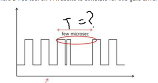
    What is the PWM frequency that you are using? What is the rising edge to edge time in the following diagram?

    VSENOCP:

    The sense overcurrent protection is also available on the HW device however, you only have 1 level of trip voltage setting as opposed to the 4 levels available in the SPI mode.

    Best,
    Akshay

  • Thanks & Regards

    Would you be able to provide a waveform of this? I asssume this is SHx to GND. The 1st overshoot could be due to fast turn on/ringing of MOSFETs,. I would need to analyze the waveform to comment more.

    Best,

    Akshay

  • Hey David,

    Could we know a little bit more about the application/EE for this project? What voltage rail is your system using and what the timeline for this project would be?

    Best,

    Akshay