This thread has been locked.

If you have a related question, please click the "Ask a related question" button in the top right corner. The newly created question will be automatically linked to this question.

DRV8311: The OUTx issue and schematic review

Part Number: DRV8311

Tool/software:

Hi,

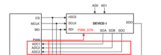
We use the DRV8311 for the BLDC which used for the drone gimbal, please refer to below screenshot, we want to know if we don't connect the SOA/SOB/SOC to MCU ADC because our MCU has no eought ADC resource,

plesae advise if this is available? BTW, if we can consider to use the SPI to read the register to get the circuit sense data, thanks.

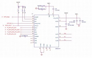
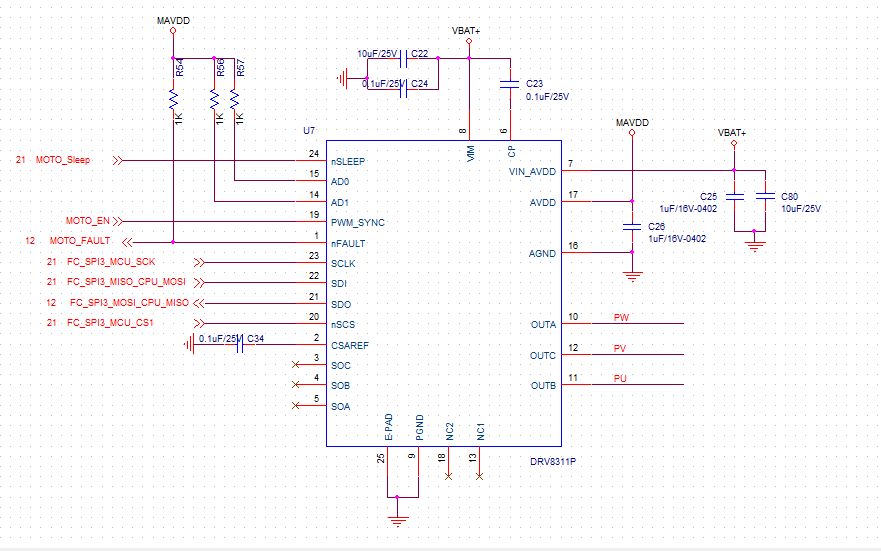
Plesae also review our schematci diagram, thanks.

  • Hi Zhang,

    CSA output cannot be read over SPI registers. The one exception is that an overcurrent fault will be reported over SPI, but the general current values will not be reported.

    Alternatively, you can combine the three SOx outputs into one using the recommendations in this FAQ: https://e2e.ti.com/support/motor-drivers-group/motor-drivers/f/motor-drivers-forum/1219254/faq-how-to-convert-3-csa-outputs-to-one-with-bldc-integrated-fet-drivers?tisearch=e2e-sitesearch&keymatch=what%20to%20do%20with%20unused%20csa%20pins#.

    If you're already measuring phase current in a different way or don't need current measurements at all, then you can leave SOx floating.

    Let me know if this helps.

    Best,

    Davis

  • Hi Davis,

     Thanks for your kindly reply.

    Now, we have a support need for the DRV8311.

    Because the DRV8311 is used for the BLDC driver and it is used in the Drone gimbal control, we want the BLDC meet the following requirements:

    1. Plesae advise if we need use the BLDC is open-loop control if we have no current sensor?

    2. We need the motor rotation angle less or equal to than 1°, that we can control the camera more accurate;

    3. Please advise how to avoid the the problem of starting vibration in BLDC;

    4. If DRV8311 is support the Low current mode? How to count the minimum current value? 

    Pleas also review our schematic diagram and advise if there are any error, thanks.

  • Hi Zhang,

    1. To clarify, do you mean that you will not monitor the current sense output, or that you will not have a Hall sensor? This video might be able to provide some more information on what is needed for open and closed loop control: https://www.youtube.com/watch?v=S28P3ZTD9ws.

    2. I will need to look into this information with my team and provide an answer next week.

    3. To avoid unexpected movement on startup, I would recommend using an algorithm such as initial position detection. This method is outlined in the video I linked about.

    4. There is a low power mode that is initiated when nSLEEP is pulled low. The datasheet provides parameters for current draw when this occurs. 

    The schematic looks fine, just remember to disable the CSAREF undervoltage fault if you do not supply any voltage to CSAREF if you are not using it.

    Please let me know if this answers your questions in the meantime, and I will get back to you on question 2 soon.

    Best,

    Davis

  • Hi Davis,

    Thanks for your kindly suppot;

    1. To clarify, do you mean that you will not monitor the current sense output, or that you will not have a Hall sensor? This video might be able to provide some more information on what is needed for open and closed loop control: https://www.youtube.com/watch?v=S28P3ZTD9ws.

    Sorry, we have no assess to open the YOUTUBE video because of the China's policies, so please check if there are any other channel to look your video?

    2. I will need to look into this information with my team and provide an answer next week.

    This is very appreciate to the supoort of your and your team's , we will wait for your reply;

    3. To avoid unexpected movement on startup, I would recommend using an algorithm such as initial position detection. This method is outlined in the video I linked about.

    Based your suggestion, we add the position sensor for the motor rotor initial position detection and we can get the position sensor signal to MCU for the SPI control, is it right?

    4. There is a low power mode that is initiated when nSLEEP is pulled low. The datasheet provides parameters for current draw when this occurs. 

    Sorry, my question mean that if the motor otates slowly, the bus current is very small, so we want to know if the DRV8311 is support the low current mode, thaks.

    The schematic looks fine, just remember to disable the CSAREF undervoltage fault if you do not supply any voltage to CSAREF if you are not using it.

    This is very fine for your reply that our schematic is OK, we look forward to your reply to provide the solution for above issue, thanks.

  • Hi Zhang,

    Try this link for the video: https://www.ti.com/video/6269668413001#tab-1. Let me know if it works, I might need to consult with my team to find a different way to share this information with you.

    Initial Position Detection is actually a sensorless algorithm that uses voltage pulses in the motor coils to measure back EMF to find the rotor position. The video explains it in more detail if you are able to access it. Alternatively, using a position sensor such as an absolute encoder should give you the position of the rotor without having to spin it, and you should be able to enter closed loop acceleration instantly.

    Lastly, you should be able to output low current from the DRV8311 if the torque output from the rotor is small. the DRV8311 can handle up to 5A peak output, but anything less than that is possible as long as the algorithm can control it.

    Best,

    Davis

  • Hi Zhang,

    I am still looking into the resolution of position control. Can you please confirm whether you intend to use an encoder, Hall sensors, or sensorless control?

    Best,

    Davis

  • Hi Zhang,

    I just wanted to follow up on my previous message to understand more about the system. This will help me determine recommendations for getting the desired precision. Please let me know if you have any information.

    Best,

    Davis

  • Hi Davis,

    We will add the hall sensor for the position loop, the hall sensor like the Melexis MLX90381 or other, thanks.

    MLX90381-Datasheet-Melexis.pdf

  • Hi Zhang,

    It appears that this Hall sensor provides a total angular error of 1 degree with dynamic compensation in the XY magnetic axis. The precision of the motor control from the DRV8311 will depend on both the precision of this Hall sensor and the efficiency of the software algorithm.

    Best,

    Davis

  • Hi Davis,

    OK, many thanks for your kindly support, we will finish our design and test fistly.

  • Hi Zhang,

    Sounds good! I am going to close this thread now but please resolve this thread/reply/start a new thread if you have questions after you test.

    Best,

    Davis