This thread has been locked.

If you have a related question, please click the "Ask a related question" button in the top right corner. The newly created question will be automatically linked to this question.

DRV8871: DRV8871-Technical problem

Part Number: DRV8871

Tool/software:

Hi ti team,

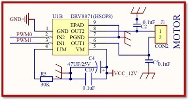
1. We originally expected to rely on the overcurrent stall protection function of the IC to avoid the risk of finger pinch in our product (due to product design issues, it is necessary to achieve anti-pinch by means of the IC or other methods). However, during the testing process, we noticed the following problems, making it difficult to achieve our expectations: When the product gearbox is operating normally (without the addition of the ILIM resistor), the working current is approximately 130 to 140 milliamps, and the maximum current at the instant the gearbox gets stuck is approximately 220 to 300 milliamps. The DC internal resistance of the motor is 7.5 ohms and the power supply is 12 volts.

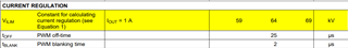
1. When the ILIM resistor is set to 320 kiloohms, the theoretical overcurrent stall current should be 200 milliamps, but at this time, the IC has automatically adjusted the motor current to 120 to 130 milliamps internally. The motor gearbox operates normally, but when simulating a finger pinch that forcibly jams the gearbox and immediately releases the finger, the motor fails to resume operation, and the current remains at approximately 20 to 30 milliamps.

2. When the ILIM resistor is set to 256 kiloohms, the theoretical overcurrent stall current should be 250 milliamps, but at this time, the IC has automatically adjusted the motor current to 120 to 140 milliamps internally. The motor gearbox operates normally, but when simulating a finger pinch that forcibly jams the gearbox and immediately releases the finger, the motor fails to resume operation, and the current remains at approximately 20 to 30 milliamps.

3. When the ILIM resistor is set to 213 kiloohms, the theoretical overcurrent stall current should be 300 milliamps. At this time, the IC has automatically adjusted the motor current to 130 to 160 milliamps internally. The motor gearbox operates normally, but when simulating a finger pinch that forcibly jams the gearbox, the motor fails to start and stop, failing to achieve the purpose of anti-pinch.

Therefore, we expect to have a deeper understanding of the performance of this IC and request support:

1. How much difference should be set between the working current of the motor and the stop current at least to achieve effective stop?

2. Is the failure of the motor to resume startup after start and stop caused by the too small setting of the stop current?

3. What is the minimum stop current that can be set for DRV8871? 4. For the above cases, how should it be set to achieve a more ideal stop protection function? What we expect is to start and stop the motor when the finger just gets caught in the gearbox, instead of waiting until the gearbox is completely stuck (preferably start and stop at a current of 200 to 250 milliamps)

  • Hello,

    The current regulation trip threshold (ITRIP) will depend on the range of VILIM and the resistor component tolerance of RILIM. When using RILIM = 320kΩ the range of VILIM is anywhere from 184mA to 216mA. This range can be calculated using the desired RILIM and VILIM min/max range from datasheet.

    What motor is being used?

    What is the stall current rating of the motor?

    What is the application? If possible, I would also consider using one of our newer integrated motor drivers that offer an integrated Stall Detection feature like the DRV8235.

    Best,

    David

  • Hi David,

    What motor is being used?

    [KW]Gear motor, see the attached brief specification.

    What is the stall current rating of the motor?

    [KW]We have tried to stall the motor using plastic rod, just simulate the human finger stuck into the tube accidentally, found the current only increase 40mA. However, we would like to detect this current then stop motor movement.

    What is the application? If possible, I would also consider using one of our newer integrated motor drivers that offer an integrated Stall Detection feature like the DRV8235.

    [KW]The application is pet cleaner, see the attached vide.

    馬達連牙箱.docx

  • Hello, 

    It is possible the load is drawing to much current and the device is exceeding the OCP threshold or getting too hot and tripping the TSD. 

    If possible, could you please provide a picture of the schematic and layout?

    Best,

    David

  • Hi David,

    It is possible the load is drawing to much current and the device is exceeding the OCP threshold or getting too hot and tripping the TSD. 

    [KW]Without current limit condition, our working current just around 130~140mA, motor stall current around 220~300mA. So, don’t think the device is exceeding the OCP threshold or getting hot then tripped the TSD. Please see the below message in Chinese for easy understand our problem.

    If possible, could you please provide a picture of the schematic and layout?

    [KW]The motor schematic as below, since program not started yet, so we are using 3.3V DC level input to the DRV8871 motor driving IC for testing.

  • Hello,

    How are you applying your input signals? Are you using PWM on any inputs or running one at 100% duty cycle and one low?

    Without using RLIM, and applying VM = 12V with Rload = 7.5Ω you should be seeing around 1.6A through your load if you are driving at 100% duty cycle. How did you determine the DC internal resistance of the motor, was it in the datasheet or measured?

    Best,

    David