This thread has been locked.

If you have a related question, please click the "Ask a related question" button in the top right corner. The newly created question will be automatically linked to this question.

UCC28180: PFC

Part Number: UCC28180

Tool/software:

Hi,

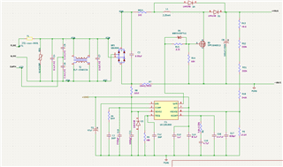
I have been planning to use UCC28180 in my 110W motor drive solution.

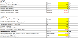
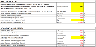
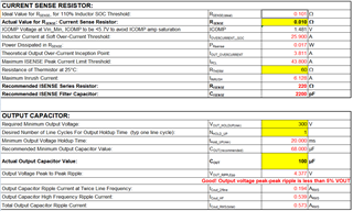
I have tested with UCC28180EVM-573 its working fine, But its designed for 350W, What are the values I have to change to fit it to my 110W application.

Regards,

Manikandan.

  • Hello Manikandan, 

    Please fill out this Excel-based calculator tool with your design targets and it will generate the component values that you will need for 110W:

    https://www.ti.com/tool/download/SLUC506

    Regards,
    Ulrich

  • Hello Ulrich,

    Thank you for the calculation sheet.

    I have calculated the required value for 110W application and designed it with my power section, Kindly give your feedback on the design.

    Kindly suggest if any changes required.

    Regards,

    Manikandan.

  • Hello Manikandan, 

    Thanks for the schematic diagram and screen-shots of the Excel design tool. 
    The schematic circuit is basically in the correct form, however the values may not be appropriate for your application.
    The "power" diodes are definitely only place-holder symbols using small-signal logic diode part numbers, and the schematic looks like it is copied from some existing source, not an original design. 

    In several places of the calculator tool, the user inputs are far different from the recommended values.  But in particular, the boost inductance and current sense resistance are significantly different.  Some deviation usually can be accommodated, but in these cases, I recommend to modify the values to be closer to what is recommended by the tool. 

    In the future, I suggest that it would be easier to support you if you upload a copy of your excel file rather than loading many screen shots of it. 

    Regards,
    Ulrich

  • Hello Ulrich,

    I have copied the schematic from UCC28180EVM-573 evaluation board only,

    And the boost inductor and current sense resistor values have been calculated as per the data sheet only.

    I have attached the excel sheet kindly change the values as per our application.sluc506c.xls

    Regards,

    Manikandan.

  • Hello Manikandan, 

    The excel sheet that you provided has an over-written cell at C116.  In your screen shot above it previously had a recommended value of 0.101ohm.

    I have revised your Excel file with some changes that I recommend:
    1.  The orange colored cells are values that I changed so that the recommended Lboost and Cin values match what you had already chosen.
    2.  The blue colored cells are values that I changed to provide better performance.  (Your previously chosen value for Rs was 10mR, where the recommended value is 101mR.  I changed it to 100mR.)

    Here is the modified file: 
    SLUC506C_E2E_1393309(mod).xls

    I think that the ripple current you will obtain with 2.25mH will be rather large and lead to high THDi at high line. 
    I suggest to reduce the % of ripple (at cell C64) and use the higher Lb value that is recommended.  

    Regards,
    Ulrich

  • Hi,

    Thank you for your design support,I will test and give feedback.

    Regards,

    C.Manikandan