This thread has been locked.

If you have a related question, please click the "Ask a related question" button in the top right corner. The newly created question will be automatically linked to this question.

DRV8825: Motor drivers forum

Other Parts Discussed in Thread: DRV8825

Tool/software:

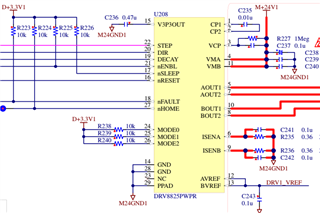
We using PDRV8825WPR stepper motor control driver. I found a old thread it has looks complete same.

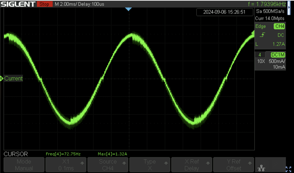
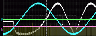
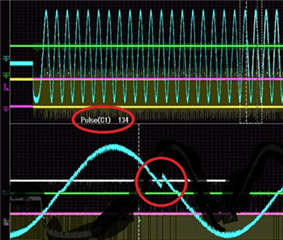
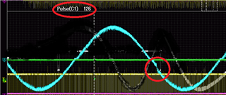
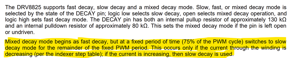
We have two lots, old one is complete OK however new lot has problem. Almost half  has "Step loss problem". We check all signal and adjusted "Decay Mode" also . The symptoms happened only new lot. We always buy from authorized dealers.

Mr. Huiqi Li, please let me know what was loot problem and how to solved, if you look my thread.

Best regards

Ted Suzuki

  • Hello Suzuki-san,

    Thanks for posting in this forum. Could you please confirm the actual part number and the marking on the IC shows PDRV8825? A "PDRV" instead of "DRV" indicates a pre-production device. This product was released in 2010 so a "PDRV" should not exist for this product. A picture of the top side of the IC would be helpful.

    As regards to step loss problem, could your please describe this in detail. Coil current waveforms with details on VM supply voltage, current setting, uStep mode, step rate etc would be helpful and if possible the schematic diagram. Thank you.

    Regards, Murugavel

  • Hello Murugavel,

    Thank you for support.

    Actual part number is DRV8825WPR not added P. I made a mistake when I copied it.
    I'm currently gathering the technical information regarding this problem. I'll back, Please give me a little time.

    Regards,

    Ted

  • Hello Suzuki-san,

    Sure. I will wait for the information from you. Thanks.

    Regards, Murugavel

  • Hello Murugavel and Expert,


    It's been a while, but I've found what seems to be the cause. However, I don't have any clear proof, so I'd appreciate some advice.


    Simply explain the problem,

    When the board was completed, the first lot was fine, but when the lot was changed, about 1/2 boards sometimes out-of-step symptom.


    Below is the actual circuit diagram.


    The person in charge said that he used the circuit of TI's evaluation board as a reference.

    Below is the TI circuit diagram.

    My concern is how C will affect with the current detection (resistor.)

    The calculation for current detection is as follows from the data sheet.

    8.3.2 Current Regulation (TI Sec sheet)

    Example : VREF/(5x 0.36ohm)


    Our design current value is 1.46A.

    This current is the rated value of the pulse motor. In other words, it is designed to be driven with almost full power current.

    The motor specifications are as follows.

    PKP246D15A2 (Oriental Motor)

    Resistance (each phase) 2.9 Ω

    Inductance (each phase) 7.9 mH

    Rated current 1.5 A/phase


    Going back to the first about C,

    The design does not take into account the effect of this capacitor.

    In fact, it seems that the IC is controlled by a current above the rated current.

    It depends on the driving speed of the FET in the IC and the characteristics of the elements such as the capacitor, but it is not clear to what extent the current is limited.


    If we assume that it is controlled at about 1 μSec, Z at 1 MHz is about 1.6 Ω, so

    2.63/(5*0.29)=1.63A  (0.29 mean parallel 0.36 Ω + 1.6 Ω )


    From the above, I can think of the following,:

    1. Maximum rated current is flowing.
    2. The drive speed in the IC varies depending on the lot, and flowing a current above the rated current causes step-out.
    3. The current protection (OCP) is temporarily activated due to the influence of C (tDEG Overcurrent deglitch time 3µs) There is a deglitch time, which may not be correct.


    Additionally, the motor is driven at a very low load and low rotation. However, it is driven by a belt drive, so there is a possibility of unexpected backlash.

    PKP246D15A2 (Oriental motor)

    24mNm/800mNm (Very LOW load almost 1/33 of rated torque)

    87rpm, Maximum rotation speed 

    Please advise on the possible causes from the above.

    Regards,

    Ted


  • Hi

    Thank you for your question. Murugavel will back office in next week. 

  • Hello Suzuki-san,

    Thank you for getting back to us with further details.

    Going back to the first about C,

    The design does not take into account the effect of this capacitor.

    In fact, it seems that the IC is controlled by a current above the rated current.

    The C of 0.1 uF across the sense resistor of 0.36 Ω does not affect current regulation. The time constant of this RC is pretty low compared to the current regulation chopping frequency which may be around 50 kHz. It is not necessary to use this capacitor. However there is no impact to current regulation with this value of C.

    So based on the schematic for 0.36 Ω Rsense and VREF = 2.63 V, the set current should be about 1.46 A. Also MODE0,1,2 pins are HIGH in the schematic suggesting 32 uSteps mode. In microstepping mode for proper current decay during current regulation switching, either Mixed decay or Fast decay must be used else the decreasing current of the sine current 2nd and 4th quadrant and currents of small amplitudes will not achieve proper regulation and waveform will be distorted potentially causing missed steps

    I have an EVM for this device with me. It can support up to 2.5 V for VREF, so with 0.4 Ω the set current should be 1.25 A. I tested it with a 2.1 Ω, 4 mH stepper with no load and with a 24 V motor supply. This EVM has these 0.1 uF capacitors as shown in the EVM schematic.

    See below current waveform with Mixed decay setting Stepper at 87 RPM or 9280 PPS. The waveform was very clean with expected full-scale current IFS = 1.25 A. Based on this waveform the current regulation works as expected at these settings and should be able to achieve the expected stepping accuracy.

    Could we please get a capture of the current waveform for one of the coils A or B for review? Thank you.

    Regards, Murugavel

  • Hello Murugavel and Expert,

    Thank you for your advice.

     Regarding C, I understood that it does not directly affect the detection of the current. I did not realize that the chopping frequency was 50KHz. I was thinking of a more higher frequency.

    Going back to the main topic,

      About the decade and drive waveform, we currently using FAST decay mode. Below is the waveform flowing the coil current.  (Blue Waveform)

    Looking at this waveform, the drive and brake appear to be normal, I think.

     The problem is a little complicated.

    In micro stepping mode (1/32 STEP), the sine wave returns to the initial zero in 128 steps. At this time, nHOME (Home Position) is output. Therefore, the number of pulses until the next nHOME should be 128 pulses. The problem here is that there are rare times when this is not the case. (The number of pulses is more or less.)

    134 pulses (128+6) 

    126 pulses (128-2)   opposite direction

    It looks like the phase suddenly advances or delays by several steps in the middle of the sine wave.

    If you imagine it, it looks like the level generator using the up/down counter inside the IC is operating at an incorrect step level due to some influence. This phenomenon does not occur with old lots, only new lots.

    The inductance and current of the motor currently being used are relatively large, and it may be that a surge caused by the back EMF of the coil is affecting the malfunction., What do you think?

    Regards,

    Ted

  • Hello Suzuki-san,

    Thank you for sharing the current waveforms.

    Regarding C, I understood that it does not directly affect the detection of the current. I did not realize that the chopping frequency was 50KHz. I was thinking of a more higher frequency.

    Matter of fact, the DRV8825 uses a fixed frequency PWM for current regulation. The TYP value for this f is 30 kHz.

    This phenomenon does not occur with old lots, only new lots.

    I think the anomalies you circled in the current waveforms are a result of fast decay and the variations in the ITRIP comparator offset between device to devices. The offset it trimmed at the factory to close to zero. However, it is impossible to achieve true zero offset. It is still possible some devices may have slightly different offsets but within specifications. This could affect current regulation behavior near the zero current based on the supply voltage, stepper L and R and the decay mode used.

    The inductance and current of the motor currently being used are relatively large, and it may be that a surge caused by the back EMF of the coil is affecting the malfunction., What do you think?

    True, current decay behavior is affected by BEMF of the coil. The effect may be profound while using fast decay (bridge reversal) near zero. Using Mixed decay should mitigate this issue. Mixed decay uses only slow decay for increasing currents, 1 and 3 quadrants and uses 75 % fast and 25 % slow combination for decreasing currents, 2 and 4 quadrants of the sine wave. 


    The current waveform I shared was with Mixed decay operation. Please try with Mixed decay and capture the current waveforms. I think this should address the anomaly at close to zero crossings as well as fix the missed step(s). Thank you.

    Regards, Murugavel 

  • Hello Murugavel and Expert,


    PWM f. is 30 kHz.

    OK Understood, I also checked the data sheet and found that..

    Actually, this problem is not mine's  and my neighborhood’s product, so I have never used this driver myself. Therefore, I did not fully read and understand the data sheet. However, I was curious about the problem and what the cause was, so I asked about it on this forum.

    Going back to the decay mode,

    The current waveform with Mixed decay mode,

    It looks much better than the Fast mode

      They had data all 3 modes.  The slow mode is not good, but the Mixed mode is looks better than the Fast. I don't know why they didn't adopt this, but I'd like to test it again with the mixed. I'll post the results again.

    I am basically analog engineer, so I agree with your explanation. I not clearly know how the PWM is controlled from the comparator without errors, but I think it is well done. However, the fast mode, which flows current in the opposite direction, directly affects the current detection of the comparator, so care must be taken. It seems safer not to use the fast decay (bridge inversion) mode, at least near zero.

    I'll post the results again if I get.

    Thank you.

    Ted

  • Hello Suzuki-san,

    Actually, this problem is not mine's  and my neighborhood’s product, so I have never used this driver myself. Therefore, I did not fully read and understand the data sheet. However, I was curious about the problem and what the cause was, so I asked about it on this forum.

    I see. I understand. Thanks.

    The current waveform with Mixed decay mode,

    Yes this looks pretty good and zero crossing looks good. I do not see any missing steps. So this hopefully should resolve the issue. 

    I did notice unexpected glitchy current after the motor stopped - red circle. Was the VREF changed to reduce the current? This could cause an unwanted movement of the motor.

    I am basically analog engineer, so I agree with your explanation. I not clearly know how the PWM is controlled from the comparator without errors, but I think it is well done. However, the fast mode, which flows current in the opposite direction, directly affects the current detection of the comparator, so care must be taken. It seems safer not to use the fast decay (bridge inversion) mode, at least near zero.

    Yes, you are correct.

    I'll post the results again if I get.

    Thank you.

    Regards, Murugavel