This thread has been locked.

If you have a related question, please click the "Ask a related question" button in the top right corner. The newly created question will be automatically linked to this question.

DRV8350H-EVM: Hall Sensor input, 1xPWM Mode

Part Number: DRV8350H-EVM

Tool/software:

Hello.

I am John.
I am designing a BLDC motor drive with DRV8350H.

I am writing this because I have a question about the circuit design.

My product receives PWM speed command from an external MCU and operates a BLDC motor based on the hall sensor signal.

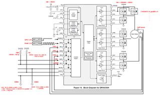
Q1. VDRAIN voltage is 48V, can I input 48V as VM power?

Q2. Can I connect the low side FET source to GND?

Q3. Can this design be operated with square wave six-step BLDC motor control?
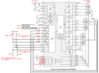
Q4. If SOA, SOB, SOC of DRV8353H shunt resistor type are not connected to an external MCU, is the motor control characteristic the same square wave 6-step control as DRV8350H?

Can it not be operated with FOC control?
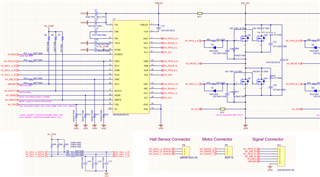
Q5. Below is my circuit diagram. Please let me know if there is any error.
  • Hi John, 

    Thank you for posting to our forum! 

    Please allow me to look over this information and provide feedback by next week after review. 

    Best Regards,

    -Joshua

  • Hello.
    I look forward to your feedback.
    Thank you.

  • Hi John, 

    I was able to go ahead and look over everything now, so please find my feedback below:

    Q1. VDRAIN voltage is 48V, can I input 48V as VM power?

    Yes, the input supply VM can range from 9V to 75V. You also have the option of split supply architecture if you want VM to be supplied at a different value than VDRAIN.

    Q2. Can I connect the low side FET source to GND?

    Yes, the low-side sources (SLX) will connect to GND for the DRV8350-H.

    Q3. Can this design be operated with square wave six-step BLDC motor control?

    Yes, the device can operate in 1x PWM mode with 6-step block commutation. Please refer to section 8.3.1.1 of the DRV835x datasheet for further details regarding commutation tables and options.

    Q4. If SOA, SOB, SOC of DRV8353H shunt resistor type are not connected to an external MCU, is the motor control characteristic the same square wave 6-step control as DRV8350H?

    Can it not be operated with FOC control?

    If not using the CSAs (SOx outputs) for motor feedback, then the HALL states of the motor will be required for motor commutation.

    Q5. Below is my circuit diagram. Please let me know if there is any error.

    The only major feedback I have for this design is to lower the IDRIVE gate current setting form 1A/2A source/sink, to a much lower value. You may easily burn out your MOSFETs if trying to switch so quickly. We recommend a rise/fall time of 100ns - 300ns for most applications, which should be achievable with a lower IDRIVE configuration.

    Please see this E2E FAQ for further details: https://e2e.ti.com/support/motor-drivers-group/motor-drivers/f/motor-drivers-forum/796378/faq-selecting-the-best-idrive-setting-and-why-this-is-essential?tisearch=e2e-sitesearch&keymatch=idrive#

    I hope this information has been helpful, and please reach out further if you have additional questions!

    Best Regards,

    -Joshua

  • Question about your Q4 answer
    : If I don't use CSA(SOx output) for motor feedback, does connecting HALL status of motor for motor commutation mean external MCU? Or does it mean connecting to INLA, INHB, INLB?

    If I connect hall signal to INLA, INHB, INLB, will FOC control not be possible and only 6-stpe control is possible?

  • Hi John, 

    In 1x pwm mode either an external MCU or the HALL states (HALL_A, HALL_B, HALL_C) can drive the inputs (INLA, INHB, INLB).

    Only the 6-step commutation will be possible in the configuration as you are using the hall states for input.  

    Is FOC/ sensorless FOC a requirement for this application?

    Best Regards, 

    -Joshua