Other Parts Discussed in Thread: , DRV8434S, DRV8452, DRV8461EVM, DRV8461, MSP-MOTOR-CONTROL
Tool/software:
Me and my colleagues are investigating an issue where we observe different different maximum current values depending on stepping speed which understandably results in change in torque.
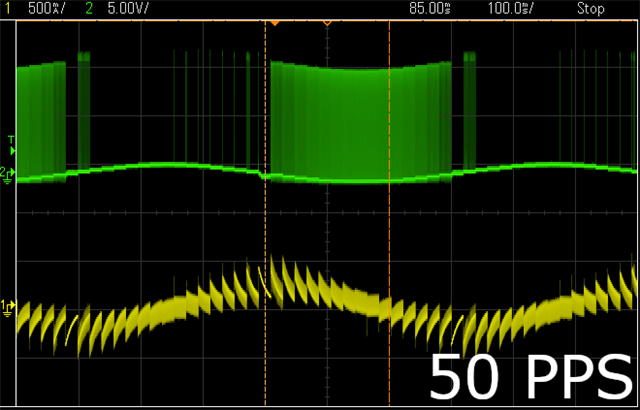
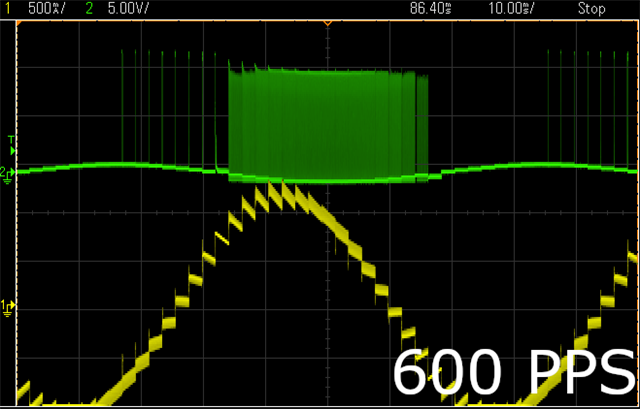
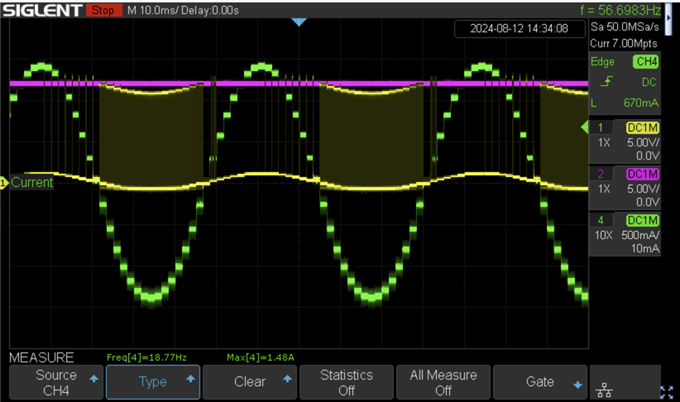
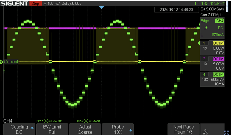
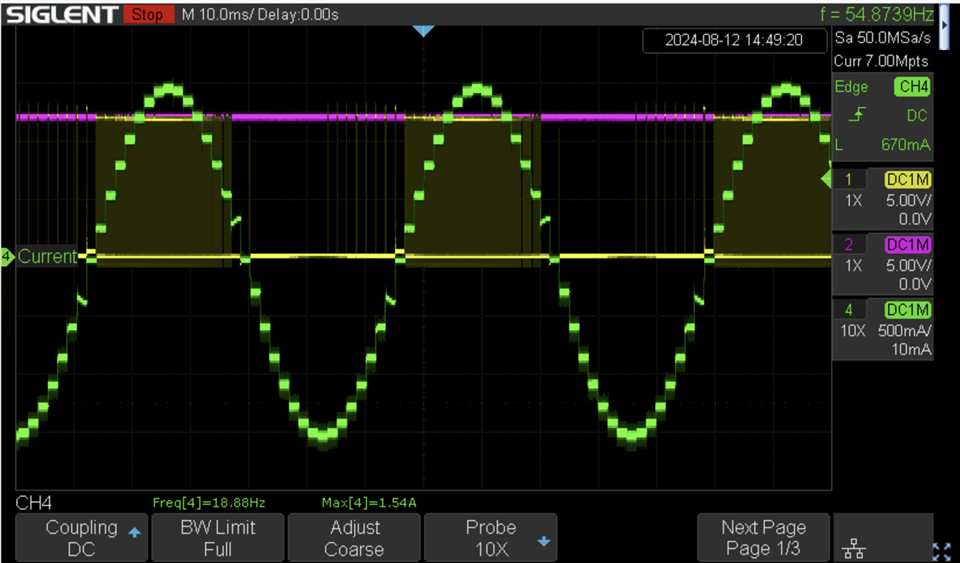
In current case TRQ_DAC is set to 100%, Vref has stable 3V3 supplied to it and we're operating in 1/8 microstepping with Smart Tune Ripple Control. Our motor coils both have 0.9 ohm and 0.9 mH and the driver VM is powered from 12V, 1.5A supply.
Please see pictures below - green channel is A1 output voltage, yellow is A1 output current. When stepping with 50 PPS we can see the max current reaching roughly around 500mA while with the same settings but at 600 PPS we observe more than twice as much. Can somebody please give us a hint on how to increase current output at lower stepping frequencies (and in consequence the torque which is the most important for us right now)?