This thread has been locked.

If you have a related question, please click the "Ask a related question" button in the top right corner. The newly created question will be automatically linked to this question.

DRV8350H-EVM: MOSFET VDS overcurrent protection (OCP) question

Part Number: DRV8350H-EVM

Tool/software:

Hi team

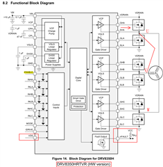
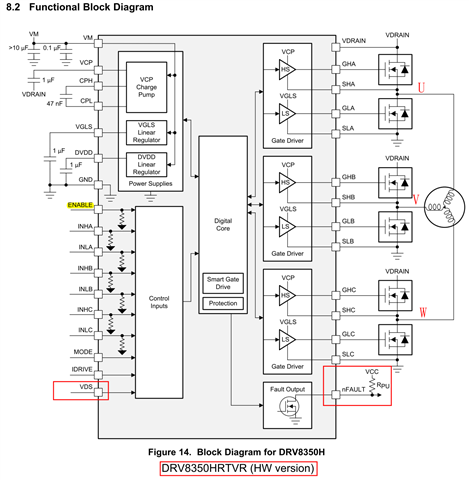
I use Device : DRV8350HRTVR (HW version)

Some question below

1. Does VDS protection detection protect "all six-arm" MOSFET?

2. The protection set by this VDS pin. Is it suitable for "all six-arm" MOSFET?

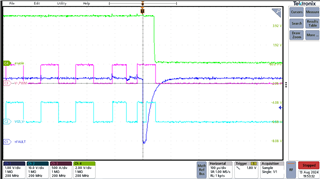
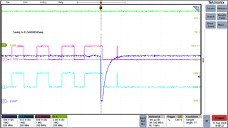
3. When overcurrent is triggered, will "all input" PWM signals(INHA~C & INLA~C) turned off?

Or only the arm of the overcurrent MOSFET (EX INHA)?

4. When overcurrent is triggered, nFault H-->L,how long will nFault to recover to H? (If INHA~C & INLA~C signals continues input)

Thanks~

  • Update 

    3. When overcurrent is triggered, will "all output" PWM signals(GHA~C &GLA~C) turned off?

  • Hey Chihhsuan,

    Thank you for the question. I have assigned this to a team member to provide feedback.

    Best,

    Akshay

  • Hi Chihhsuan,

    1. Yes, each MOSFET on each phase is monitored for VDS overcurrent.

    2. The VDS pin is used to select the voltage threshold at which each of the VDS monitors will report an overcurrent. Please see the Electrical Characteristics table in the datasheet for information on how to configure the VDS_OCP threshold voltage for a hardware device. All monitors will use this setting as the threshold.

    3. During a VDS overcurrent event, all MOSFETs are disabled, not just that specific one.

    4. The DRV8350H has an automatic retry time of 8ms, as well as cycle-by-cycle mode where a new rising edge on a PWM input will clear the fault. You can refer to section 8.3.6.3 of the datasheet for more information.

    Best,

    Davis

  • Hi Davis

    Thanks for the reply.

    I test  : Short with U phase & V phase (refer below figure 1)

    and find out the waveform below

    when nFault happen, DRV8350HRTVR still output the PWM signal

    Figure 2--> VGS,W-

    Figure 3-->VGS,V- & VGS,W-

    Figure 1

    Figure 2

    Figure 3

    CH1 VGS,U- (GLA-SLA)

    CH2 VGS,V- (GLB-SLB)

    CH3 VGS,W- (GLC-SLC)

    CH4 nFAULT (Pin 17)

  • Hi Chihhsuan,

    To clarify, the concern is that Vgs is still high after the fault? I will need to look into this information and aim to provide more feedback early next week.

    Best,

    Davis

  • Hi Chihhsuan,

    Could you please provide an image of the INLx signal simultaneous with this Vgs output? This will help me understand the input-output relationship for this circumstance. Additionally, have you confirmed that a VDS_OCP event has occurred? There is a possibility that a thermal warning might trigger nFAULT to go low while leaving the gate outputs unaffected, but I would need to confirm whether the device has this feature.

    Best,

    Davis

  • Hi Davis

    Thanks for the reply. Please refer below.

    Figure 1 when UV short happen, can measure the CH3 Iu,peak=170Apk, and nFAULT H-->L, so I think the OPC is triggered.

    CH1 VGS,U-

    CH2 VGS,V-

    CH3 Iu,short

    CH4 nFAULT (Pin 17)

    Figure 1

    Figure 2 shows INLx signal simultaneous with this Vgs output

    CH1 nFAULT

    CH2 VGS,V-

    CH3 V-,PWM (INLB)

    CH4 Enable (Pin 22)

    Figure 2 (Can find out when nFAULT happen, VGS,V- turned off)

    Figure 3 (Can find out when nFAULT happen, VGS,V- still output)

    In this test, work in Ta=25°C & light load & open frame, so I think thermal warning is Slim chance.

    4. The DRV8350H has an automatic retry time of 8ms, as well as cycle-by-cycle mode where a new rising edge on a PWM input will clear the fault. You can refer to section 8.3.6.3 of the datasheet for more information.

    -->So, if I use cycle-by-cycle mode, even can't know the nFault keep low min time?

  • Hi Chihhsuan,

    Thank you for the information. I would agree, it appears to be an overcurrent event. In regards to your last question, nFAULT is just a digital indication that a fault has occurred, and its timing after the overcurrent event is related to the propagation through the digital logic, which should theoretically also disable the gate outputs. So, there shouldn't be a minimum low time for nFAULT. However, I will need to discuss this information with my team and hope to provide more feedback by tomorrow at the latest.

    Best,

    Davis

  • Hi Chihhsuan,

    After consulting my team, it appears that individual phase overcurrent shutdown is possible. According to the datasheet, this is the default setting on the SPI device, so I will need to confirm whether this applies to the hardware device as well. Note that this means that the whole half bridge is disabled, not individual MOSFETs.

    This would explain why the W phase doesn't shut down in one of the images you sent, and when other phases don't shut down, this might be due to the overcurrent event occurring in another phase slightly earlier.

    Thank you for your patience while I confirm what the default mode for the hardware device is.

    Best,

    Davis

  • Hi Chihhsuan,

    I can confirm the default for the DRV8350H is to shut down only the associated phase with the overcurrent event. Please let me know if you have any additional questions.

    Best,

    Davis

  • Sorry for late reply, thanks a lot !!