This thread has been locked.

If you have a related question, please click the "Ask a related question" button in the top right corner. The newly created question will be automatically linked to this question.

DRV8870: DRV8870DDA, over current absoring.

Part Number: DRV8870


Tool/software:

Hi,

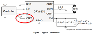
For operating one of the our motor, we are using  the your DRV8870DDA motor driver.

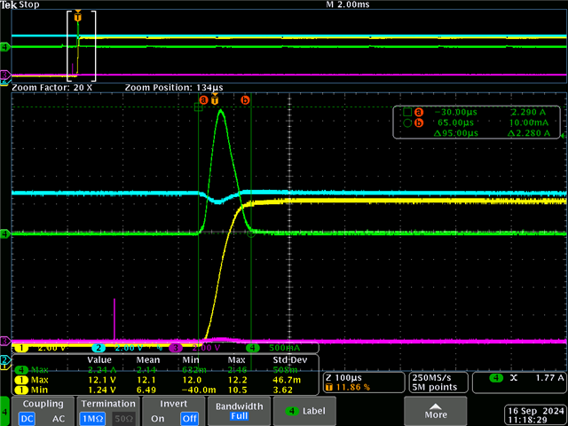
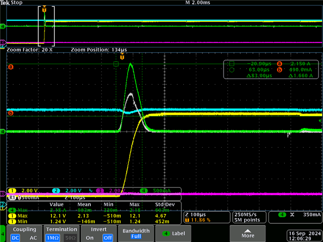
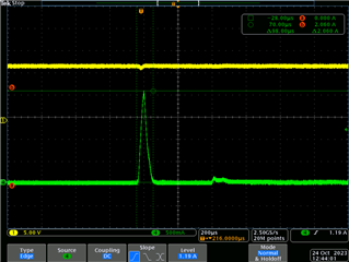
As you can see from the file (current_absorbed_peak.png) attached, we have a current absorbed peak about 2A (duration is about  100usec).

This peak is increasing up to 3A, when we will remove the protection of the external power supply. 

The Motor is powred by 6V, generated by the specifically internal dc/dc converter. The main pcb motherboard is powered at 12Vdc. 

According to the imposed limitation of the motor current peak, our expectation is to have a maximum current peak <1.3A. Please, observe that the absorbed peak is happening, even if the motor is not driven (motor stopeed), just when the power of the DRV is started. 

We also measured the ports of the microcontrolle (motor P, MotorN ---IN1 and IN2) and the gate waves seams to be on sync, Never overlying.  

Question for you are:

- Do you have any idea about the cause of this over peak

- Any suggestion to remove or at least to mitigate this defect.

Available for replying if you will need other info from us.

Attached you can find a draft of the schematic, motoer, datasheet and measures of the current peak. 

Thanks,

BR,

CA.

current peak on the motor

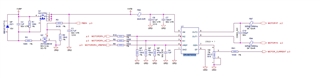
draft of the shcematic
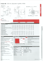
motor datasheet. 

  • Hello,

    Please allow me 24 hours to look into these issues. 

    Best,

    David

  • Hi Carlo,

    The current spike you are seeing called motor inrush current. This occurs as soon as a motor voltage is applied. As the motor datasheet says, at 6V the motor resistance R = 1.82Ω, allowing I = V/R = 3.3A. As the back-EMF builds across the motor this current will decrease, however, there are still some ways to reduce this inrush current. 

    The motor driver will protect itself by disabling the outputs when the motor current exceeds IOCP =~ 3.7A for a duration of tOCP =~ 1.5us. It sounds like the current regulation threshold (ITRIP) is set to 1.3A? This is a good way to reduce the amount of inrush current, but if the inrush current is still significant, another way to reduce this is to slowly ramp up the inputs. Try slowly increasing the duty cycle of the PWM inputs. 

    Best,

    David

  • Hi David, Thank you for your suggestions.

    Please read the below just to better be aligned about the situation. 

    We repeated the same measurements disconnecting the cable from the motor (motor disconnected):

    Blue-wave: V_DC_input.

    Green-wave: A_Input current absorbed.

    Yellow-wave: VM (Vinput of the Driver, which is switching on) 

    Violet-Wave: is the pin2 or 3 of the driver (see the schematic draft below)

    Please, also see below the current really absorbed by the Driver itself (this measure was realized, simply replacing FB3---see schematic draft--with a short...cable) 

    Blue-wave: V_DC_input.

    Green-wave: A_Input current absorbed.

    Yellow-wave: VM (Vinput of the Driver, which is switching on) 

    Violet-Wave: is the pin2 or 3 of the driver (see the schematic draft below)

    Gray-wave is the input current absorbed by the driver itself (about 1A).

    It seams that >1A the driver is absorbing by itself, even if the motor is disconnected.

    Let me know,

    BR,

    CA.

  • Hi CA.,

    This does seem strange. The device should not be drawing that much current without a load attached. Would like to look more into the schematic just to verify connections. Do you see any noticeable solder blobs or pin shorts near any of the pins? 

    I can't find the schematic you mentioned, could you please resend? 

    Is the V_DC (blue signal) the VREF input?

    Best,

    David