This thread has been locked.

If you have a related question, please click the "Ask a related question" button in the top right corner. The newly created question will be automatically linked to this question.

DRV8350: Motor drivers forum

Part Number: DRV8350

Tool/software:

Dear Ti team

First, we're using "DRV8350R" part.

I have a question about this part.

IDRIVE Setting.

As you can see 9.2.1.2.2 IDRIVE Configuration in datasheet

we can calculate IDRIVEP, IDRIVEN values. like bellow Equations.

also, Our MOSFET part is IPTC014N08NM5*2 parallel for 3 phase inverter.

you can see bellow values ​​in IPTC014N08NM5 datasheet.

- Qgd: 45nC (max)

-Rise Time: 15ns

- Fall Time: 46ns

So, I can calculate like this

IDRIVEP = 45*2nC / 4.6ns = 6A

IDRIVEN = 8.8nC / 4ns = 1.95A

Finally, Can I set IDRIVE to "1/2 A"?

I think my calculation result(6A/1.95A), is larger than the setting value(1A/2 A), what should I do in this case?

Did I calculate it right?
I think belows time is too short.

So, I think raise time and fall time are generally about 100 ns ~ 300 ns. like in datasheet (9.2.1.2.2.1 IDRIVE Example) is it right?

=>Could you tell me how much Rise Time and Fall Time should normally be set and calculated?

-----------------------------------------------

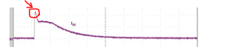
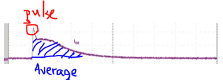
In addition, I currently have an external 15ohm Rg resistor in series. By measuring the voltage at both ends, I can get the output driving current as shown in the following diagram:
I would like to ask if the IC is set (1A/2A) and the peak pulse of Turn on exceeds 1A (actually measured is about 2A)
Will this affect the IC? How can I confirm that this will not overload the driver IC?
Or is there nothing to worry about as long as the switch can switch normally?

  • Hello,

    Typically for rise and falls times we recommend 100ns - 300ns. Try to avoid using the highest IDRIVE setting since this can cause ringing and potential damage.

    For more information on choosing the correct IDRIVE setting please refer to the following FAQ:

    https://e2e.ti.com/support/motor-drivers-group/motor-drivers/f/motor-drivers-forum/796378/faq-selecting-the-best-idrive-setting-and-why-this-is-essential

    If you have concerns please provide the following waveforms:

    GHx to SHx 

    SHx to GND

    GLx to GND

    Regards,

    Yara

  • Hi Yara

    Thanks for the response
    for what you mentioned

    1."Try to avoid using the highest IDRIVE setting since this can cause ringing and potential damage."
    I am adding more external RGs to adjust the response and confirm that there will be no RINING phenomenon. If so, will there still be the potential damage you mentioned?

    2.In addition, I would like to ask the following questions
    According to the peak sink gate current 2000mA and peak source gate current 1000mA of DRV8350R in the figure below
    =>Does this refer to average current? Shouldn’t it refer to Pulse current?

    Because I don't quite understand what you mean when you write "Internally limited" in the output current section of absolute.
    Does it mean that it will limit itself internally, so we don’t have to worry about the output exceeding it instantly?

    For example, I know ucc27514, which writes Output continuous source/sink current & Output pulsed source/sink current (0.5 µs) in the absolute section.

    Based on the above mentioned, please help me confirm, thank you

  • Hello Yuhsiang,

    I am adding more external RGs to adjust the response and confirm that there will be no RINING phenomenon. If so, will there still be the potential damage you mentioned?

    How much gate resistance are you adding? Too much can also damage the device and cause certain features that rely on VDS and VGS data to be affected.

    According to the peak sink gate current 2000mA and peak source gate current 1000mA of DRV8350R in the figure below
    =>Does this refer to average current? Shouldn’t it refer to Pulse current?

    I highly recommend taking a look at the following app note: https://www.ti.com/lit/an/slva714d/slva714d.pdf?ts=1727454207658

    Because I don't quite understand what you mean when you write "Internally limited" in the output current section of absolute.
    Does it mean that it will limit itself internally, so we don’t have to worry about the output exceeding it instantly?

    I believe when the datasheet states "internally limited" its referring to the fact that the user is setting the sink and source current, however I'll have to double check this with my team.

    I should also mention based of Qgd of the MOSFET you've selected and the FAQ I link early that explains selecting the best IDRIVE for your system, the IDRIVE setting should be in the range of 150mA to 450mA.

    Regards,

    Yara