This thread has been locked.

If you have a related question, please click the "Ask a related question" button in the top right corner. The newly created question will be automatically linked to this question.

DRV8705-Q1: Overcurrent trigger behavior

Part Number: DRV8705-Q1
Other Parts Discussed in Thread: CSD18512Q5B

Tool/software:

Hello Team,

We are utilizing the CSA output analog voltage information from the motor driver (DRV8705S), converting it to digital using the MCU (STM32) ADC, and determining whether the current exceeds the set threshold.

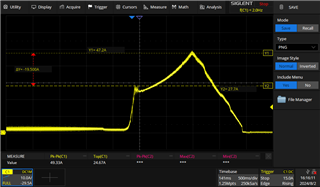
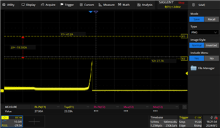
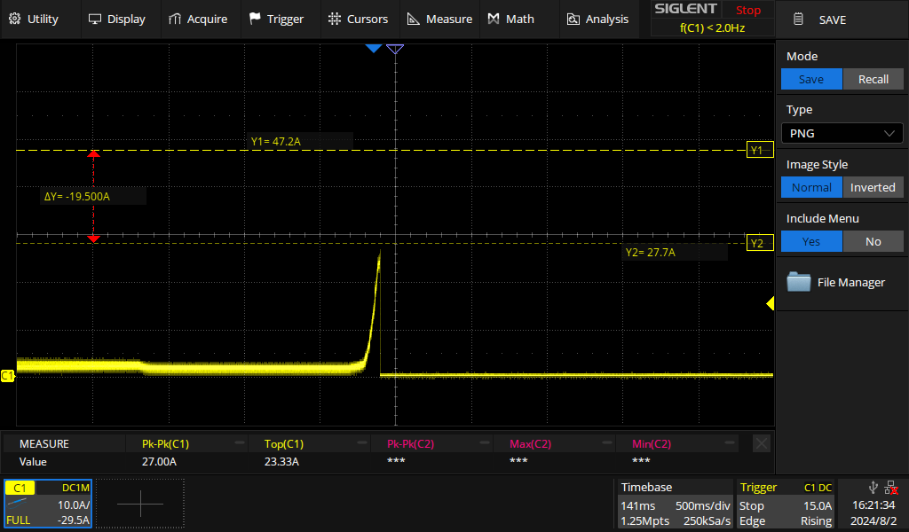
Currently, we have configured a 15A current threshold in the MCU firmware using the internal ADC. When the motor crosses this threshold, we observe an overcurrent trigger; however, during this event, the motor current peaks at 49A before the driver shuts off. Below is the overcurrent waveform of the motor.

Also, currently in firmware we have set the VDS threshold to 0.12V, but when we attempt to lower the VDS threshold to 0.10V, the motor gets stuck.

Is there any other option to reduce this peak current? We want the driver to shut off below 20A, as our motors are rated for 15A.

  • Hi Sonali,

    What do you mean by the motor gets stuck? The fault is getting latched?

    Can you use a lower VDS threshold for this application?

    Are you using the SPI variant?

    If so you can set the OCP deglitch time to something lower than the default value of 4 us:

    Another option to be add more inductance in series with the motor to slow down the current rise.

    Would you able to capture the output signals on the plot as well. What is the action taken once it crosses the threshold?

    Best,

    Keerthi

  • What do you mean by the motor gets stuck? The fault is getting latched? : 

    Ans: When overcurrent is triggered in normal operation (with VDS set to 0.12V or 0.16V), the motor speed reduces smoothly and gradually from 90% to 0%, and it stops. However, when VDS is set to 0.10V, the motor stops abruptly when overcurrent is triggered. Please refer to the waveforms below for reference.

    VDS: 0.16V or 0.12V

    VDS: 0.10V or 0.06V


    Can you use a lower VDS threshold for this application?

    Ans: Yes, we can, but as explained above, performance is negatively affected when we reduce the VDS threshold.

    Are you using the SPI variant?

    Ans: Yes, we are using the DRV8705SQRHBRQ1.

    If so you can set the OCP deglitch time to something lower than the default value of 4 us:

    Ans: Currently, we have set the OCP deglitch time to 8 μs. We will try lowering it and test again.

    Another option to be add more inductance in series with the motor to slow down the current rise.

    Ans: The boards are currently in the production stage, so a design change may be difficult at this point. Please find the attached schematic for your reference.

    Would you able to capture the output signals on the plot as well. What is the action taken once it crosses the threshold?

    Ans: When the current crosses the threshold (15A in our case), we set the motor speed to zero and raise an error. How should we capture the signals on the plot? we are using the current probe to measure motor current.

  • Hello, 

    The boards are in the production stage, but our client has allowed us to make both hardware and software changes to resolve this issue. We would greatly appreciate your assistance in addressing this. Please find the attached schematic for your reference.

    IO_Controller_V3.0.1.pdf

    Let us know if you need more information.

    Thanks,

    Sonali

  • Hi Sonali,

    I will take a look at the schematic, but can you tell me where you are measuring this current. Is this by the load, the power supply current, etc.

    Just to clarify after this point the motor speed is set to zero, so how are you decaying the current (e.g. low side active free wheel). I am trying to understand why the current is going up after you set the motor speed to 0.

    Best,

    Keerthi

  • Hello Keerthivasan,

    We are measuring the motor current (load current) using current probes compatible with oscilloscopes. 

     we are using PH/EN H-Bridge Control with Low-side freewheeling.

    Sonali

  • We have provided the register mapping in our firmware for your reference.

    CONTROL Register  
    1) IC_CTRL Register (Address = 4h) [reset = 6h]  
    Bit Field Description  
    7 EN_DRV 1b = Gate driver outputs are enabled and controlled by the digital inputs.  
    6 SSC_DIS 0b = Enabled.  
    5 IN1/EN_MODE 0b = IN1/EN signal is sourced from the IN1/EN pin.  
    4 IN2/PH_MODE 0b = IN2/PH signal is sourced from the IN2/PH pin  
    3-1 LOCK 011b = Unlock all control registers.  
    0 CLR_FLT 1b = Clear faults, resets to 0b after completion.  
           
    2) BRG_CTRL Register (Address = 5h) [reset = 0h]  
    Bit Field Description  
    7 VGS_HS_DIS 0b = Enabled.  
    6-5 BRG_MODE 01b = PH/EN H-bridge input control.  
    4 BRG_FW 0b = Low-side freewheeling.  
    3 S_IN1/EN Control bit for IN1/EN input signal. Enabled through IN1/EN_MODE bit.  
    2 S_IN2/PH Control bit for IN2/PH input signal. Enabled through IN2/PH_MODE bit.  
    1 S_HIZ1 0b = Outputs follow IN1/EN signal.


    0 S_HIZ2 0b = Outputs follow IN2/PH signal.  
           
    3) DRV_CTRL_1 Register (Address = 6h) [reset = Ffh]  
    Bit Field Description  
    7-4 IDRVP_HS 1111b = 62 mA Mosfet - CSD18512Q5B
    IDRIVE = QgD/ tRiseFall
    = 13.3nC/100nS
    = 133mA
    IDRIVE = QgD/ tRiseFall
    = 13.3nC/300nS
    = 44.33mA
    3-0 IDRVN_HS
    1111b = 62 mA
     
           
    4) DRV_CTRL_2 Register (Address = 7h) [reset = Ffh]  
    Bit Field Description  
    7-4 IDRVP_LS 1111b = 62 mA  
    3-0 IDRVN_LS 1111b = 62 mA  
           
    5) DRV_CTRL_3 Register (Address = 8h) [reset = 20h]  
    Bit Field Description  
    7-6 VGS_MODE 00b = Latched fault.  
    5-4 VGS_TDRV 10b = 4 µs  
    3-1 VGS_TDEAD Insertable digital dead-time.
    010b = 500 ns
     
    0 VGS_IND 0b = Disabled.  
           
    6) VDS_CTRL_1 Register (Address = 9h) [reset = 20h]  
    Bit Field Description  
    7-6 VDS_MODE 00b = Latched fault.  
    5-4 VDS_DG 11b = 8 µs  
    3-2 VDS_IDRVN 00b = Programmed IDRVN  
    1 VGS_LVL VGS monitor threshold for dead-time handshake and gate fault
    detection.
    0b = 1.4 V.
    1b = 1.0 V
     
    0 VDS_IND 0b = Disabled.  
           
    7) VDS_CTRL_2 Register (Address = Ah) [reset = Ddh]  
    Bit Field Description  
    7-4 VDS_HS_LVL 0101b = 0.16 V Mosfet - CSD18512Q5B
    Overcurrent threshold,
    0.16 V/1.3 mOHM = 123 A
    3-0 VDS_LS_LVL 0101b = 0.16 V  
           
    8) OLSC_CTRL Register (Address = Bh) [reset = 0h]  
    Bit Field Description  
    7-5 RESERVED Reserved  
    4 OLSC_EN 0b = Disabled.  
    3 PU_SH1 0b = Disabled.  
    2 PD_SH1 0b = Disabled.  
    1 PU_SH2 0b = Disabled.  
    0 PD_SH2 0b = Disabled.  
           
    9) UVOV_CTRL Register (Address = Ch) [reset = 14h]  
    Bit Field Description  
    7 PVDD_UV_MODE 0b = Latched fault.  
    6-5 PVDD_OV_MODE 00b = Latched fault.  
    4-3 PVDD_OV_DG 11b = 8 µs  
    2 PVDD_OV_LVL 1b = 28.5 V  
    1 VCP_UV_MODE 0b = Latched fault.  
    0 VCP_UV_LVL 0b = 2.5 V  
           
    10) CSA_CTRL Register (Address = Dh) [reset = 1h]  
    Bit Field Description  
    7 CSA_SH_EN 0b = Disabled  
    6 CSA_BLK_SEL 0b = Half-bridge 1  
    5-3 CSA_BLK 000b = 0 %, Disabled  
    2 CSA_DIV 0b = AREF / 2  
    1-0 CSA_GAIN 01b = 20 V/V
  • Is there any update on this?

  • Please provide an update on this. This is urgent for us, and any assistance or feedback would be greatly appreciated.

  • Hi Sonali,

    Can you capture something like this?

    Best,

    Keerthi

  • Hello Keerthivasan,

    1) Motor in running condition

    Yellow: Fault, Pink: +24V_Mot, Blue: Motor current, Green: GH1(Gate)

    2) Motor in overcurrent condition

    Yellow: Fault, Pink: +24V_Mot, Blue: Motor current, Green: GH1(Gate)

    Thanks,

    Sonali

  • Hi Sonali,

    There are a couple things to address from the waveform. You need more bulk capacitance on the board, so your supply doesn't dip so much. Please see App note on how to size bulk capacitance:

    Bulk Capacitor Sizing for DC Motor Drive Applications

    It also looks like the VDS setting has no impact as there is no Fault, and it looks the current limiting is due your firmware. The supply dipping also explains why there is 2 different rates of current increase. 

    Can you capture the same waveforms for this case:

    Best,

    Keerthi

  • Hello,

    We have added bulk capacitors per the Evaluation kit schematic. Below is our schematic, we have added each 470uF and 1uF capacitor pair near each high-side MOSFET of the motor driver section. Let us know if we need more bulk capacitors. 

    We are working on the waveform you need. We will send you soon.

    Thanks,

    Sonali

  • Hi Sonali,

    It looks like there bulk capacitance on the board should be sufficient. What are you using currently to power the board (power supply, battery)? I am just trying to understand why the supply is folding back.

    Best,

    Keerthi

  • Hello Keerthivasan,

    We use a 24Vdc at 18.8A (HRP-450-24) power supply to power the board.

    Please find the waveforms for VDS: 0.10V or 0.06V where our motor is getting stuck.

    1) Motor in running condition

    Pink: Fault, Yellow: +24V_Mot, Blue: Motor current, Green: GH1(Gate)


    2) Motor in overcurrent condition

    Pink: Fault, Yellow: +24V_Mot, Blue: Motor current, Green: GH1(Gate)

    Thanks,

    Sonali

  • Is there any update on this?

  • Hi Sonali,

    It looks like you are getting a fault in the second waveform you have sent.

    Can you double check once what fault it is?

    Just to clarify the issue is that the motor is getting stuck after this fault? What application is this going in?

    Best,

    Keerthi

  • Hello,

    Can we arrange a team call to explain our application and the issue we are facing? This will help us resolve it as soon as possible.

    If yes, could you please share your email ID and let us know a suitable date and time for the call?

    Looking forward to your response.

    Thanks,

    sonali

  • Hi Sonali,

    Let me get back to you on this request.

    Best,

    Keerthi

  • Hello,

    Is there any update on this?

    Thanks,

    Sonali

  • Hi Sonali,

    I will send an email.

    Best,

    Keerthi

  • Hello,

    Is there any update on this?

    Thanks,

    Sonali

  • Hi Sonali,

    I have sent you an email.

    Best,

    Keerthi

  • Hello Keerthi,

    I haven't received any email from you. Could you please confirm which email address you sent it from?

    Thanks,

    Sonali

  • I will message you the email address that I see on my side.

    Best,

    Keerthi

  • Hello Keerthi,

    I have mailed you from the email id sonaliz@acevin.com. Can you please let us know a time that would be convenient for you? 

    Thanks,

    Sonali

  • Hi Sonali,

    I have emailed you back.

    Best,

    Keerthi

  • Hello Keerthi,

    The board already has a 470uF (bulk) and 1uF (bypass) capacitor pair near each high-side MOSFET in the motor driver section. We have now added an additional 100uF bulk capacitor in parallel with the 470uF.

    Please see the waveform below with the added bulk capacitance:

    Pink: SO (CSA output), Yellow: +24V_Mot, Blue: Motor current

    We did not observe any significant difference in voltage drop after adding the extra bulk capacitance.

    Thanks,

    Sonali

  • Hello Keerthi,

    We have generated the same overcurrent condition on the DRV8705S Eval kit. Below are the observations.

    1) Set-up Image:

    2) VDS: 0.14V, Max current: 48A, No overcurrent fault triggers

    3) VDS: 0.10V, Overcurrent trigger at: 44A

    4) VDS: 0.08V, Overcurrent trigger at: 36.67A

    5) VDS: 0.06V, Overcurrent trigger at: 28.67A

    Thanks,

    Sonali

  • Hello Keerthi, 

    Please find the attached layout file.

    1016.IO_Controller Rev3.0.PcbDoc

    Thanks,

    Sonali

  • Hi Sonali,

    Thanks for attaching the layout. I will take a look, and we can discuss tomorrow.

    Best,

    Keerthi

  • Hello Keerthi,

    1) The Below waveform is for the DRV8705S eval kit with SO and nFault signa.

    Vds:0.06v, Yellow: SO, and Green: nFault

    2) We changed the VDS_MODE from Latched Fault to Cycle-by-Cycle on the Eval Kit. See the waveform below. The motor did not stop in this condition.

    3) Below are the logs of the gate driver error when VDS is set to 0.06. 

    /* *************** */
    Status Reg: 0x9cc2, Error Reg: 0x210, Control Reg1: 0x601, Control Reg2: 0x0
    M1_Cur: 0 A, M2_Cur: 0 A, M3_Cur: 0 A
    M1_RealCur: 0 A, M2_RealCur: 0 A, M3_RealCur: 0 A
    M1_RawCur: 2064 raw, M2_RawCur: 2060 raw, M3_RawCur: 2059 raw
    Motor 1: 0 V, Motor 2: 0 V, Motor 3: 0 V
    +24Vsig: 2765 V, +24IOsig: 2715 V, +15Vsig: 1716 V, VBat: 68 V, 230V_Cntr: 30, DigPower1: 2703 V, DigPower2: 2686 V,
    Analog1: 930, Analog2: 0, SW-Version: 196608, HW-Version: 196608
    Temp1: -566 C, Temp2: -371 C, PcbTemp: 4477 C, PcbHumity: 4959 %
    Digital Input: 0x6fe , 1790, keepAlive: 0 , acVoK: 1, mainSwitchEn: 1
    ToggleSignal: 255, BatteryLoadEn: 0, BackupSupply: 0
    Windspeed_MB: 0, Windspeed_FC: 0, MB_WatchdogMinVal: 157
    GateDriver1 Status:
    Error on gate Driver Status Reg1: 0xe8a8
    Error on gate Driver Status Reg2: 0xe808
    Error on gate Driver Status Reg3: 0xe800

    /* *************** */
    Status Reg: 0x9cc2, Error Reg: 0x210, Control Reg1: 0x601, Control Reg2: 0x0
    M1_Cur: 18 A, M2_Cur: 0 A, M3_Cur: 0 A
    M1_RealCur: 18 A, M2_RealCur: 0 A, M3_RealCur: 0 A
    M1_RawCur: 2064 raw, M2_RawCur: 2063 raw, M3_RawCur: 2058 raw
    Motor 1: 0 V, Motor 2: 0 V, Motor 3: 0 V
    +24Vsig: 2763 V, +24IOsig: 2718 V, +15Vsig: 1722 V, VBat: 67 V, 230V_Cntr: 20, DigPower1: 2716 V, DigPower2: 2727 V,
    Analog1: 932, Analog2: 0, SW-Version: 196608, HW-Version: 196608
    Temp1: -633 C, Temp2: -340 C, PcbTemp: 4500 C, PcbHumity: 4944 %
    Digital Input: 0x6fe , 1790, keepAlive: 0 , acVoK: 1, mainSwitchEn: 1
    ToggleSignal: 0, BatteryLoadEn: 0, BackupSupply: 0
    Windspeed_MB: 0, Windspeed_FC: 0, MB_WatchdogMinVal: 157
    GateDriver1 Status:
    Error on gate Driver Status Reg1: 0xe8a8
    Error on gate Driver Status Reg2: 0xe808
    Error on gate Driver Status Reg3: 0xe800


    Thanks,

    Sonali


  • Hi Sonali,

    I have sent invite.

    Best,

    Keerthi

  • Hello,

    I am attaching the motor datasheet for your reference. We use models EC100.240 and EC180.240.

    I_EC_IP66-DC-electric-motors_210513_0521.pdf

  • Hi Sonali,

    Thank you for attaching. I will look into this.

    Best,

    Keerthi

  • Hello,

    1) Sample and hold firmware

    Blue: motor current, Yellow: SP wrt SN,   

    2) VDS: 0.06V, ADC Threshold: 15A

    Green: 24V_Mot supply, Blue: Motor current

    Thanks,

    Sonali

  • Hi Sonali,

    Can you capture SO once. I will schedule a meeting to discuss.

    Best,

    Keerthi