


Tool/software:
Hi everyone,
I am Anjali from Merai Newage Pvt. Ltd. Chennai. We are designing a board to drive two brushed DC motors in two linear actuators used to lift some weight. We are using the DRV8243 SPI (S) variant in the application.
In the first attempt, we used the same bulk capacitor as given in the evaluation board, 10µF, which we realized was not sufficient for the motors inrush current.
Below are the observed motor characteristics.
Peak continuous current consumed by motor (I) : 2.5 A
Inrush current at beginning (I'): 6 A
Duration of inrush peak (dt): 15 ms
Voltage (VM): 24 V
Based on above values, I calculated the required capacitance to be 1880µF. [ C * V = ∆I * dt ]
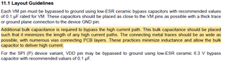
The datasheet recommends to reduce the path of high current to minimize inductance. However, due to the huge size of bulk capacitors, the length of high current path on our PCB increases.
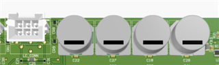
Seen above, white motor connector and 4 bulk capacitors in parallel giving equivalent capacitance 1880µF.
Please let me know if my calculations of the bulk capacitors are correct. Please also suggest a way to reduce the high current path.
Thank-you and Warm Regards,
Anjali Karmude
