This thread has been locked.

If you have a related question, please click the "Ask a related question" button in the top right corner. The newly created question will be automatically linked to this question.

DRV8424: Stepper Motor Chopping Inconsistently

Part Number: DRV8424

Tool/software:

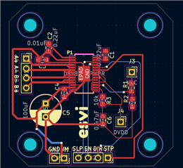
Hi, I'm working on designing and programming a PCB with the DRV8424 parts. I'm running into a bit of a weird issue with motor chopping in my PCB design. 

Schematic/Layout: 
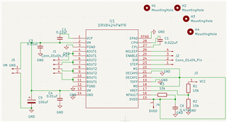
When the motor is wired as shown below, the motor does not spin or function. There is no signal coming through the A+, A-, B+, or B- pins. The DVDD shows to have 5V & the FLT pin is pulled LOW. 
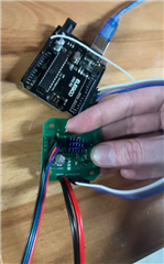
During one of my tests, I wired the FLT pin directly to the DVDD pin to force it HIGH. After doing so, I began getting this extremely choppy motion. Compared to competitors' drivers using similar code, this is far choppier and doesn't move smoothly. When any load is put on the motor, it is also unable to spin (these tests using loads that have consistently passed with two other competitor drivers). The motor's torque is the most important factor for us. I have replicated the problem across three boards, of which each fail the same way. 

Are you able to help me figure out what I did wrong with my application PCB? Thank y'all so much & I'm happy to provide any more information needed. 

Click here to play this video

  • Hi Katrina,

    Thank you for your post. I'm unable to see the image or video you may have attached. 

    During one of my tests, I wired the FLT pin directly to the DVDD pin to force it HIGH. After doing so, I began getting this extremely choppy motion.

    The nFAULT pin is an open drain FET. Tying it to DVDD directly while device is powered up would have briefly made the FET to conduct and damaging it. Not sure what else may have gotten damage within the device. This pin is an output only pin. 

    I have replicated the problem across three boards, of which each fail the same way. 

    Did you connect nFAULT in all the three boards to DVDD directly? In which case all three devices could have damaged.

    Based on your schematic you've configured the device for 1/8 Step mode, smart tune ripple control STRC decay mode. I am assuming you were using 3.3 V for VCC. This would mean VREF will be about 2 V, so IFS would be 1.5 A. This is well within the devices' capability. Generally this device drives the stepper motor pretty smoothly in the STRC decay mode. 

    What are the specifications for the stepper motor? Could you get current waveforms for either coil A or B current? What is the step frequency input? Do you use acceleration speed ramp up? Thank you.

    Regards, Murugavel