Tool/software:
Hello,
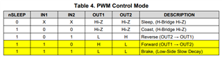
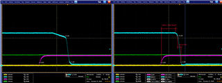
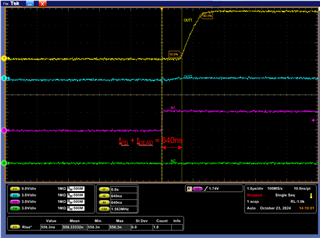
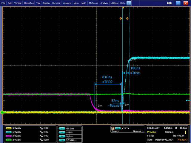
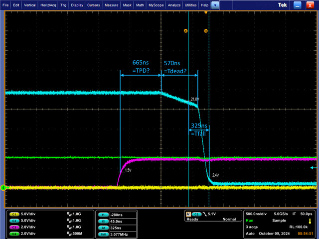
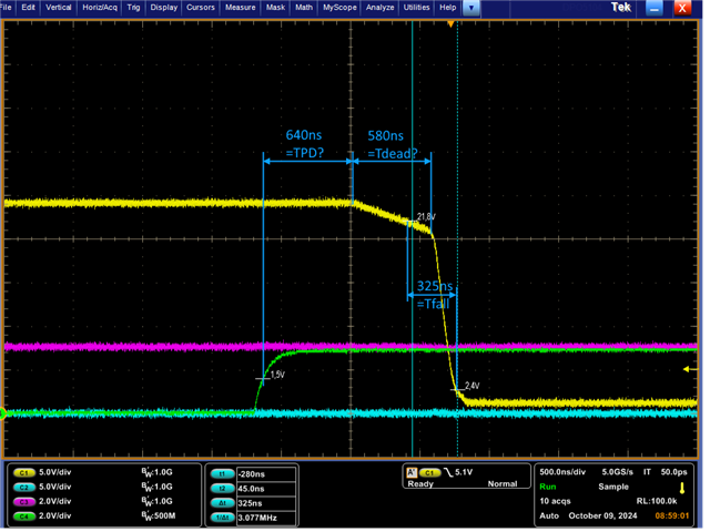
We have found that the trise, tfall, tpd, and tdead times for the DRV8874PWPR are significantly off from their typical values. In the case of tpd, there is more than a factor of 2 between the typical time specified in the datasheet and the time we measured.
Additionally, we noticed that during the falling slope, the voltage initially drops slower, and after approximately 575 ns, it starts to drop faster. I interpreted this time as the output dead time (tdead).
We also observed that the measured times correspond more closely to the automotive variant (DRV8874-Q), but we are sure that the non-automotive version is used.
Please take a look at the oscillograms and help us with the following questions:
-Are the times measured in the diagram interpreted correctly?
-What could be the reason for the times being so far off their typical values and for the unusual falling voltage curve?
The test setup is the same as stated in the datasheet: 200 Ohm from each output to GND.
CH1: OUT1
CH2: OUT2
CH3: IN1
CH4: IN2
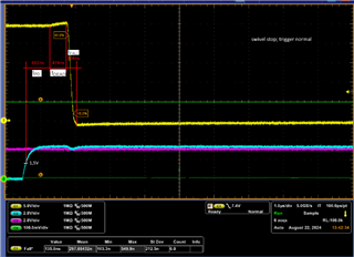
Reverse / Break:
Forward / Break: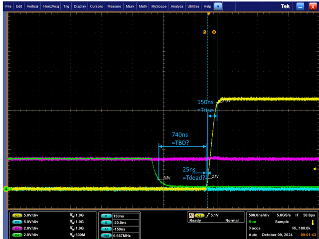
CH1: OUT1
CH2: OUT2
CH3: IN1
CH4: IN2
Thanks in advance