Tool/software:
Hi,
I've been performing some tests with the MCT8316AEVM and so far have been very impressed with the performance of the system. However, I have a few questions in regards to implementing multiple MCT units in a singe design.
The MCU I am using features a digital MUX, which allows for I2C signal to be directed to any GPIO without harming performance. This should allow me to circumvent the issue with changing the MCT's address away from 0x00. However, using 2 GPIO per MCT unit is quite costly, and as such I wish to gang them together in order to reduce GPIO cost.
This would be done by having sets of SDA GPIO and SCL GPIO such that a given SDA and SCL combination only address a single MCT unit. The other lines will be pulled high, such that all other units either have no clock signal and ignore the data, or read the data as all 1s and as such ignore the packet, since the address does not match.
Can you confirm that the MCT units will indeed ignore I2C signals if only given SDA or SCL, whilst the other line is held high? Could this cause any errors that I am not considering? It would also be acceptable to have a common clock or data line and have a separate line per MCT unit for the other, if this would be more robust.
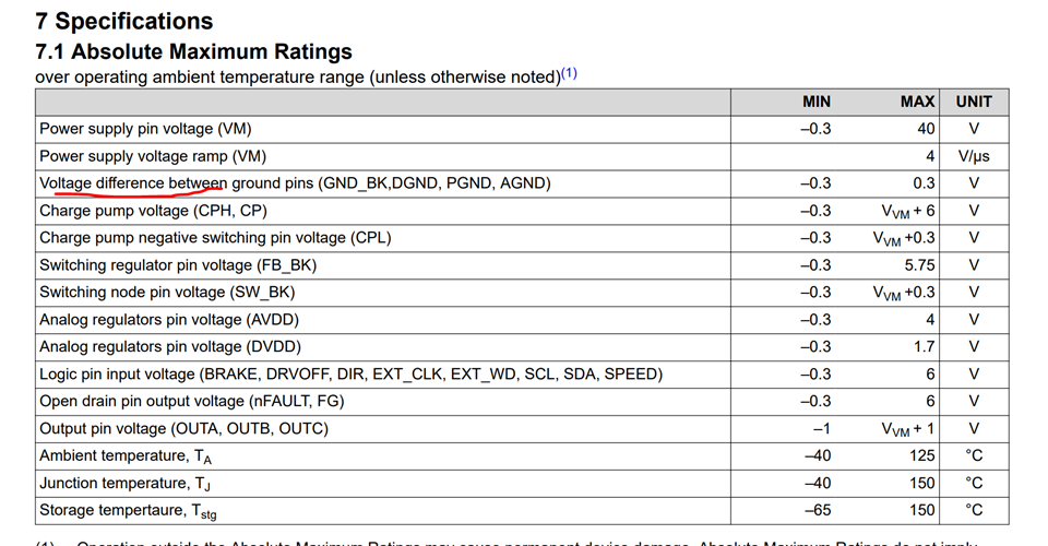
Another issue is that I wish to measure total bus current at a higher frequency than could reasonably done over I2C and without allocating analog pins to each DACOUT. I also do not want to use an external MUX or analog adder, due to form factor and cost constraints. I intend to use a current sense amplifier with a shunt, likely between GND and PGND (which should also allow ground separation to be done conveniently). This perhaps could cause up to +100mv float between PGND and AGND- might this cause issues? The alternative would be to simply run highside sensing, although this would mean perhaps a more expensive amp. Which models would you recommend for this application? Per unit cost is a major concern.
Finally, how critical is ground separation? With up to 5A/8-12V bus current peak and about 100uF of capacitance per unit, would it be very ill advised to link the PGND pins to the EPAD and simply run unified GND planes?
Thanks in advance for your time.